by Contributed | Mar 31, 2021 | Technology
This article is contributed. See the original author and article here.
Today as we develop and run application in AKS, we do not want credentials like database connection strings, keys, or secrets and certificates exposed to the outside world where an attacker could take advantage of those secrets for malicious purposes. Our application should be designed to protect customer data. AKS documentation describes in detail security best practice
In this article we will show how to implement and deploy pod security by deploying Pod managed Identity and Secrets Store CSI driver resources on Kubernetes. There are many articles and blogs that discuss this topic in detail however we will discuss how to deploy it the resources using Terraform. The source code you will find here and Azure pipeline to deploy it is here
Prerequisite resources:
The following resources should exist before running azure pipeline.
- Server Service Principal ID and Secret: Terraform will use it to access Azure and create resources. Also, will be used to integrate AKS with AAD.
- Client Service Principal ID and Secret: It will be used to integrate AKS with AAD.
- AAD Cluster Admin Group: AAD group for cluster admins
- Azure Key Vault: A KV should exists where CSI will connect with it. You can also modify the code to create the KV during the TF execution
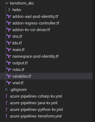
AKS Terraform Scripts Overview
Current repo has the following structure. Terraform scripts are located under “terraform_aks” folder.
Each file, under terraform_aks folder, is designed to define specific resource deployment.
- Variables.tf: terraform use this file to read custom settings variable to use during the run time. If the variable is defined in the variable file then TF expect a default value or it will be passed as env variable during execution. For example, cluster network specification
variable "virtual_network_name" {
description = "Virtual network name"
default = "aksVirtualNetwork"
}
variable "virtual_network_address_prefix" {
description = "VNET address prefix"
default = "15.0.0.0/8"
}
variable "aks_subnet_name" {
description = "Subnet Name."
default = "kubesubnet"
}
variable "aks_subnet_address_prefix" {
description = "Subnet address prefix."
default = "15.0.0.0/16"
}
- main.tf: defined different terraform providers will be use in the execution.
provider "azurerm" {
version = "~> 2.53.0"
features {}
}
terraform {
required_version = ">= 0.14.9"
# Backend variables are initialized by Azure DevOps
backend "azurerm" {}
}
data "azurerm_subscription" "current" {}
- vnet.tf: create the network resource to use with AKS based on variable.tf input
resource "azurerm_virtual_network" "demo" {
name = var.virtual_network_name
location = azurerm_resource_group.rg.location
resource_group_name = azurerm_resource_group.rg.name
address_space = [var.virtual_network_address_prefix]
subnet {
name = var.aks_subnet_name
address_prefix = var.aks_subnet_address_prefix
}
tags = var.tags
}
data "azurerm_subnet" "kubesubnet" {
name = var.aks_subnet_name
virtual_network_name = azurerm_virtual_network.demo.name
resource_group_name = var.resource_group_name
depends_on = [azurerm_virtual_network.demo]
}
- K8s.tf: The main script to create AKS. The resource configuration as following
resource "azurerm_kubernetes_cluster" "k8s" {
name = var.aks_name
location = azurerm_resource_group.rg.location
dns_prefix = var.aks_dns_prefix
resource_group_name = azurerm_resource_group.rg.name
linux_profile {
admin_username = var.vm_user_name
ssh_key {
key_data = var.public_ssh_key_path
}
}
addon_profile {
http_application_routing {
enabled = true
}
}
default_node_pool {
name = "agentpool"
node_count = var.aks_agent_count
vm_size = var.aks_agent_vm_size
os_disk_size_gb = var.aks_agent_os_disk_size
vnet_subnet_id = data.azurerm_subnet.kubesubnet.id
}
# block will be applied only if `enable` is true in var.azure_ad object
  role_based_access_control {
    azure_active_directory {
      managed = true
      admin_group_object_ids = var.azure_ad_admin_groups
    }
    enabled = true
  }

  identity {
    type = "SystemAssigned"
  }
network_profile {
network_plugin = "azure"
dns_service_ip = var.aks_dns_service_ip
docker_bridge_cidr = var.aks_docker_bridge_cidr
service_cidr = var.aks_service_cidr
}
depends_on = [
azurerm_virtual_network.demo
]
tags = var.tags
}
- To enable AAD integration we used the following configuration for the role_base_access_control section
# block will be applied only if `enable` is true in var.azure_ad object
role_based_access_control {
azure_active_directory {
managed = true
admin_group_object_ids = var.azure_ad_admin_groups
}
enabled = true
}
identity {
type = "SystemAssigned"
}
- After creating the cluster we need to add cluster role binding where we assign AAD admin group as cluster admins
resource "kubernetes_cluster_role_binding" "aad_integration" {
metadata {
name = "${var.aks_name}admins"
}
role_ref {
api_group = "rbac.authorization.k8s.io"
kind = "ClusterRole"
name = "cluster-admin"
}
subject {
kind = "Group"
name = var.aks-aad-clusteradmins
api_group = "rbac.authorization.k8s.io"
}
depends_on = [
azurerm_kubernetes_cluster.k8s
]
}
- roles.tf: this script will assign different roles to cluster and agentpool like acr image puller role
resource "azurerm_role_assignment" "acr_image_puller" {
scope = azurerm_container_registry.acr.id
role_definition_name = "AcrPull"
principal_id = azurerm_kubernetes_cluster.k8s.kubelet_identity.0.object_id
}
To Enable POD Identity. Agent pool should have two specific roles as Managed Identity Operator over the node resource group scope
resource "azurerm_role_assignment" "agentpool_msi" {
  scope                            = data.azurerm_resource_group.node_rg.id
  role_definition_name             = "Managed Identity Operator"
  principal_id                     = data.azurerm_user_assigned_identity.agentpool.principal_id
  skip_service_principal_aad_check = true

}
Virtual Machine Contributor
resource "azurerm_role_assignment" "agentpool_vm" {
  scope                            = data.azurerm_resource_group.node_rg.id
  role_definition_name             = "Virtual Machine Contributor"
  principal_id                     = data.azurerm_user_assigned_identity.agentpool.principal_id
  skip_service_principal_aad_check = true
}
Addon-aad-pod-identity.tf: The script will deploy AAD Pod identity helm chart.
Addon-kv-csi-driver.tf: The script will deploy Azure CSI Secret store provider helm chart
Namespace-pod-identity.tf: It will deploy the managed Identity for specific namespace. Also, it will deploy CSI store provider for this namespace.
Deploying AKS cluster using Azure DevOps pipeline
We can deploy the cluster using azure DevOps pipeline. In the repo there is file call “azure-pipelines-terraform.yml”
The deployment use Stage and Jobs to deploy the cluster as following.
- Task Set Terraform backed: will provision backend storage account and container to save terraform state
- task: AzureCLI@1
displayName: Set Terraform backend
condition: and(succeeded(), ${{ parameters.provisionStorage }})
inputs:
azureSubscription: ${{ parameters.TerraformBackendServiceConnection }}
scriptLocation: inlineScript
inlineScript: |
set -eu # fail on error
RG='${{ parameters.TerraformBackendResourceGroup }}'
export AZURE_STORAGE_ACCOUNT='${{ parameters.TerraformBackendStorageAccount }}'
export AZURE_STORAGE_KEY="$(az storage account keys list -g "$RG" -n "$AZURE_STORAGE_ACCOUNT" --query '[0].value' -o tsv)"
if test -z "$AZURE_STORAGE_KEY"; then
az configure --defaults group="$RG" location='${{ parameters.TerraformBackendLocation }}'
az group create -n "$RG" -o none
az storage account create -n "$AZURE_STORAGE_ACCOUNT" -o none
export AZURE_STORAGE_KEY="$(az storage account keys list -g "$RG" -n "$AZURE_STORAGE_ACCOUNT" --query '[0].value' -o tsv)"
fi
container='${{ parameters.TerraformBackendStorageContainer }}'
if ! az storage container show -n "$container" -o none 2>/dev/null; then
az storage container create -n "$container" -o none
fi
blob='${{ parameters.environment }}.tfstate'
if [[ $(az storage blob exists -c "$container" -n "$blob" --query exists) = "true" ]]; then
if [[ $(az storage blob show -c "$container" -n "$blob" --query "properties.lease.status=='locked'") = "true" ]]; then
echo "State is leased"
lock_jwt=$(az storage blob show -c "$container" -n "$blob" --query metadata.terraformlockid -o tsv)
if [ "$lock_jwt" != "" ]; then
lock_json=$(base64 -d <<< "$lock_jwt")
echo "State is locked"
jq . <<< "$lock_json"
fi
if [ "${TERRAFORM_BREAK_LEASE:-}" != "" ]; then
az storage blob lease break -c "$container" -b "$blob"
else
echo "If you're really sure you want to break the lease, rerun the pipeline with variable TERRAFORM_BREAK_LEASE set to 1."
exit 1
fi
fi
fi
addSpnToEnvironment: true
- Task Install Terraform CLI based on the parameter version.
Task Terraform Credentials: will read the SP account information that will be used to execute the pipeline
    - task: AzureCLI@1
      displayName: Terraform init
      inputs:
        azureSubscription: ${{ parameters.TerraformBackendServiceConnection }}
        scriptLocation: inlineScript
        inlineScript: |
          set -eux  # fail on error
          subscriptionId=$(az account show --query id -o tsv)
          terraform init
            -backend-config=storage_account_name=${{ parameters.TerraformBackendStorageAccount }}
            -backend-config=container_name=${{ parameters.TerraformBackendStorageContainer }}
            -backend-config=key=${{ parameters.environment }}.tfstate
            -backend-config=resource_group_name=${{ parameters.TerraformBackendResourceGroup }}
            -backend-config=subscription_id=$subscriptionId
            -backend-config=tenant_id=$tenantId
            -backend-config=client_id=$servicePrincipalId
            -backend-config=client_secret="$servicePrincipalKey"
        workingDirectory: ${{ parameters.TerraformDirectory }}
        addSpnToEnvironment: true
Task Terraform init to initiate terraform
Task Terraform apply will execute the terraform with auto-approve flag so terraform will run the apply.
P.S We could add task for terraform plan and the ask for approval.
Setting up pipeline in Azure DevOps
- Under Pipeline Library Create new variable group call it terraform and create following variables

- Add new pipeline then select Github

- After login select the terraform repo

- Select Existing Azure Pipeline YAML then select “azure-pipeline-terraform.yml”

Once we save the pipeline and created the prerequisite resources and updated the variable.tf file then we are ready to run the pipeline and we should get something like that
Check Our work
Cluster information
Under cluster configuration we should see AAD is enabled

Azure POD Identity / CSI Provider Pods
From command line we can check kube-system namespace for MIC and NMI pods


Namespace Azure Identity and Azure Identity Binding

Check for CSI secret store provider

The script was executed successfully, and all our resources and resources deployment are in place.
Summary
In this article we demonstrated how to deploy AKS integrated with AAD and deploy Pod Identity and CSI provider using terraform and helm chart. In the next article we will demo how to build application and use POD Identity to access azure resources.
by Contributed | Mar 31, 2021 | Technology
This article is contributed. See the original author and article here.
Network security requirements involve providing limited access and granting administrative permissions to users within a network. Role assignments are the way you control access to Azure back end and infrastructure resources. If the built-in roles do not meet the specific needs of your organization, Azure Role Based Access Control (RBAC) allows account owners to create custom roles that an administrator can assign to Users/User groups.
You can configure role assignments after you have defined the scope, either via Azure Portal, PowerShell, CLI or RestAPI.
In some instances, the built-in roles may be either too permissive or insufficient for the assignment that is required. Access should be provided using the principle of least privilege and every role should be carefully created with the user’s duties in mind, as a security control when creating user privileges. In this situation, you will also need to know what role actions are available.
In this article, we discuss the actions that may be used to create security conscious roles and templates that you can use to create and assign roles for Azure Firewall. Once you understand the boundaries for the role you are trying to create, you can use the template below or modify it by carefully selecting the actions required and assigning it to the user.
There are various levels of administrative roles you might be looking to assign, and this may be done at a management group level, subscription level, resource group level or resource level. Azure RBAC focuses on managing user actions at these different scopes.
To create a custom role, you must provide the following input.
{

"DisplayName": "",
"Description": "",
"Actions": [ ],
"NotActions": [ ],
"DataActions": [ ],
"NotDataActions": [ ],
"AssignableScopes": [ ]

}
You can find the description of each requirement above in this article. To configure Azure roles using PowerShell, follow the steps to create a custom role.
Click the “Deploy to Azure” button below to deploy a template for the Network infrastructure role discussed below from Github. You can use this custom template by editing the “action” field for the appropriate set of actions list in the samples below. Then provide the Principal ID(Object ID) of the user to assign the role. You can find a detailed step by step guide here.

The following 3 administrator examples are common in network scenarios:
Firewall Security Administrator
This role is assigned to an admin that is responsible for the security configurations in the network. Access control is used to manage connectivity, making sure actions are carefully assigned. This admin can analyze the security risk of each connection via the network and application rules and make changes as required.
"Microsoft.Network/azureFirewalls/networkRuleCollections/delete",
"Microsoft.Network/azurefirewalls/write",
"Microsoft.Network/azureFirewalls/applicationRuleCollections/write",
"Microsoft.Network/azureFirewalls/applicationRuleCollections/delete",
"Microsoft.Network/azureFirewalls/natRuleCollections/write",
"Microsoft.Network/azureFirewalls/natRuleCollections/delete",
"Microsoft.Network/azureFirewalls/networkRuleCollections/write",
"Microsoft.Network/azureFirewalls/networkRuleCollections/delete",
"Microsoft.Resources/deployments/*",
"Microsoft.Network/firewallPolicies/ruleCollectionGroups/write",
"Microsoft.Network/firewallPolicies/read",
"Microsoft.Resources/subscriptions/resourceGroups/read",
"Microsoft.Insights/alertRules/*",
"Microsoft.Resources/subscriptions/resourceGroups/*",
"Microsoft.Support/*"
Firewall Security Reader
This administrator requires mostly reader privileges as maybe required in an auditor role. The permission grants visibility into existing rules and other properties of the firewall. This user is therefore only able to view and not make changes
"Microsoft.Network/azurefirewalls/read",
"Microsoft.Network/azureFirewallFqdnTags/read",
"Microsoft.Network/azureFirewalls/applicationRuleCollections/read",
"Microsoft.Network/azureFirewalls/natRuleCollections/read",
"Microsoft.Network/azureFirewalls/networkRuleCollections/read",
"Microsoft.Resources/subscriptions/resourceGroups/read",
"Microsoft.Network/firewallPolicies/ruleCollectionGroups/read",
"Microsoft.Network/virtualNetworks/read",
"Microsoft.Network/firewallPolicies/read",
"Microsoft.Network/firewallPolicies/ruleCollectionGroups/read",
"Microsoft.Resources/subscriptions/resourceGroups/read"
Network Infrastructure administrator
This role has more overarching rights to change the infrastructure of the firewall from a network operations perspective, but would not necessarily need access to change network and application rules like the security admin, hence viewer access. Permissions in this role include FirewallWallPolicies attributes such as: Threat Intelligence, DNS settings, Intrusion detection etc.
"Microsoft.Network/azurefirewalls/delete",
"Microsoft.Network/azureFirewalls/networkRuleCollections/read",
"Microsoft.Network/azurefirewalls/read",
"Microsoft.Network/azureFirewalls/applicationRuleCollections/read",
"Microsoft.Network/azureFirewalls/applicationRuleCollections/read",
"Microsoft.Network/azureFirewalls/natRuleCollections/read",
"Microsoft.Network/azureFirewalls/natRuleCollections/read",
"Microsoft.Network/azureFirewalls/networkRuleCollections/read",
"Microsoft.Network/azureFirewalls/networkRuleCollections/read",
"Microsoft.Network/firewallPolicies/*",
"Microsoft.Network/ipGroups/*",
"Microsoft.Resources/deployments/*",
"Microsoft.Insights/alertRules/*",
"Microsoft.Resources/subscriptions/resourceGroups/read",
"Microsoft.Support/*",
"Microsoft.Resources/subscriptions/resourceGroups/*"
To remove the example role when done, use the following command in PowerShell:
Remove-AzRoleDefinition -Name “Custom Role - Firewall InfraAdmin"
Note: You may need the subscription owner permission if it’s the first time deploying an Azure Firewall instance in that subscription for the first deployment. This can also be achieved by registering the provider: Microsoft.ContainerService before creating the firewall.
Role Definitions use a GUID for the name, this must be unique for every role assignment on the group.
The roleDefName parameter is used to seed the guid() function with this value, change it for each deployment.
You can supply a guid or any string, as long as it has not been used before when assigning the role to the resourceGroup.
by Contributed | Mar 31, 2021 | Technology
This article is contributed. See the original author and article here.
When Microsoft Flight Simulator came out a year ago, I was completely entranced by it. I’m not particularly into hyper-accurate flight simulation games, but the concept of a game where you can go anywhere in the real world and see an accurate 3D representation of that real-world space, blew my mind. What a concept! That also got me thinking: could I make something like that myself? As a solo creator I don’t have the benefit of a team of many engineers working with map data for years.
How Flight Simulator’s World Works
Microsoft Flight Simulator uses three distinct types of world maps:
- Azure 3D Maps. Flight Simulator uses high-quality 3D photogrammetry data when it exists in Microsoft’s library. It’s pretty easy to identify these areas: there are relatively high-quality textures, but often buildings and landmarks like trees look a bit worn down as the 3D models aren’t perfect.
- AI-Augmented 2D Satellite Maps. For areas where no good 3D map data is available, Flight Simulator takes 2D satellite map footage instead. Deep learning techniques are applied to infer what sort of 3D buildings and landmarks might exist, and then a library of hand-authored 3D models are programmatically placed in the world. If you’re visiting a relatively non-descript location in Flight Sim where buildings look pristine and high-quality, you’re probably in an AI-augmented zone.
- Hand-authored content. A lot of Flight Simulator areas are modeled by hand to resemble their real-world locations. Notable examples include the hand-modeled airports in the Deluxe and Premium Deluxe editions of the game.
The second and third types of map data require an exorbitant amount of work, either designing procedural generation algorithms or doing 3D modeling and level design by hand. But the first one is doable!
Specifically, the Bing Maps SDK gives us exactly what we want: a drop-in Unity component that, given a location (via latitude/longitude coordinate pair) will render a 3D scene containing that real-world location, powered by the same 3D maps data that Flight Simulator uses. That’s so cool! I’m going to spend the remainder of this blog post walking you through setting up a pretty simple VR “flight sim” example that will let you move around a 3D representation of any location in the world!
I’m going to assume you have basic familiarity with Unity to configure a few GameObject components and write a small amount of custom code. If this is more than you’re comfortable with, please check out other tutorials to familiarize yourself with Unity’s UI.
Get a Bing Maps API Key
To use this API, you need an API key. Sign in or sign up at the Bing Maps Portal. Once you’re logged in, create a new API key by going to My account -> My Keys -> Create a new key. Name it whatever you want, choose a “Basic” key, and for now select “Dev/Test” as the application type.

After creating a key, keep this page handy, as you’ll need the key in a few minutes.
Download the Bing Maps SDK and open the sample project
For now, we’re going to use the sample starter project included with the Bing Maps SDK, although there are instructions if you would prefer to integrate the SDK manually with an existing or new project using the Unity Package Manager.
Grab the 0.10.0 release of the SDK from this page and unzip it. In Unity Hub, click “Add”, then locate this folder and select the “SampleProject” folder. If you don’t have a Unity 2019.4 release, Unity Hub may prompt you to download and install it.
Creating our scene
Start by adding a new scene by selecting File -> New Scene.
Add a new empty GameObject to your scene by right-clicking anywhere within the Hierarchy window and selecting “Create Empty”. I called mine “MapManager” (since it’s going to manage our 3D map component).

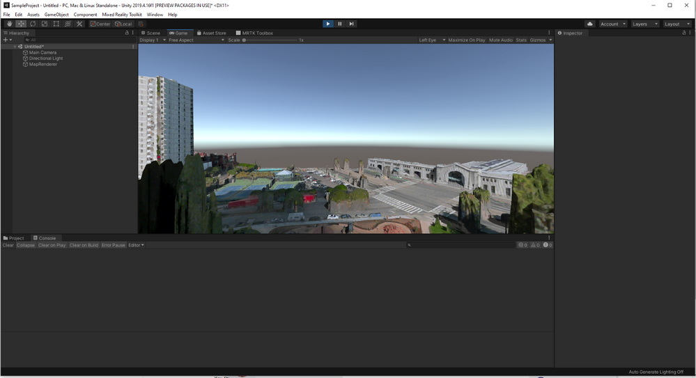
In the right-side inspector pane for this new GameObject, click the “Add Component” button and search for the “MapRenderer” component. This is a Unity component provided by the Bing Maps SDK for Unity that will automatically render our 3D map in our scene!
In the GameObject inspector pane, enter your API key from the Bing Maps Portal earlier into the Developer Key field in the Map Session pane. Add in the lat/long coordinates for the location where you want players to start their adventure into the “Location” fields at the top of Map Renderer.

I set mine to a latitude of 37.7958421 and a longitude of -122.3959688, which is the Ferry Building in downtown San Francisco. I found this by looking up the Ferry Building in Bing Maps and right-clicking the Ferry Building. If there’s a location you’d rather explore in 3D, you can get its lat/long coordinates the same way and enter them instead.
Now you will see a map of the world in your Unity scene! If you adjust the “Zoom Level” slider below latitude and longitude, you can see it zoom in on San Francisco (or your chosen location). I’ve found that setting the zoom to 19 is a good fit for our use case.


If you were to open this in VR now, it would look more like a diorama than a lush living world. Let’s make it bigger to match the scale of a person in VR! In the Transform section at the top of the inspector, set it’s the scale to (20, 20, 20). Down in the Map Layout section of the Map Renderer tab, set the Local Map Dimensions to (3, 3). This should make the map much larger and more to-scale with a human-sized VR viewer.
One final piece to the puzzle is moving the camera position. Since we’ve grown the map to be as tall as 20 units tall, but the camera is still down at the original starting point, trying to play this in VR would spawn you in the middle of the ground! Select the Main Camera object from the scene inspector, and set the camera position to (0, 12, 0). This should get you a good vantage point of the scene.
Give it a try!
Click the “Play” button in the top middle of the Unity editor now and see a fully-rendered 3D map of the location you’ve entered! If you have a VR headset connected to your computer, it should automatically render to the VR headset as well, including using head tracking to control the camera and let you look around.
Moving Around
It’s so cool that with such little work we’re already able to drop ourselves into a 3D rendering of the actual world! But we can take this further: let’s add some movement! As mentioned, I’m not particularly into detailed simulations, so for now let’s just add some super simple movement code. Hold down a button on your VR controller to move at a reasonable speed in whatever direction you are currently looking.
With our custom GameObject open in the inspector, click “Add Component”, then “New script”, and call it CameraMovement. Double-click the C# script name in the inspector to open it in your text editor of choice, then paste in the following code. Don’t worry, I’ll walk you through it in a moment!
using UnityEngine;
using Microsoft.Geospatial;
using Microsoft.Maps.Unity;

public class CameraMovement : MonoBehaviour
{
    void Update()
    {
        if (Input.GetButton("Fire1")) {
            var heading = Camera.main.transform.eulerAngles.y * Mathf.Deg2Rad;
            var speed = 0.00015f;

            var map = GetComponent<MapRenderer>();
            map.Center = new LatLon(
                map.Center.LatitudeInDegrees + speed * Mathf.Cos(heading),
                map.Center.LongitudeInDegrees + speed * Mathf.Sin(heading)
            );
        }
    }
}
Let’s walk through this!
if (Input.GetButton("Fire1")) {
Every time the Update function is called (for a VR project, usually 72 or 90 times per second), we’re going to check if the player has pressed the “Fire1” button on their VR controller. On most VR headsets, the Mixed Reality Toolkit maps this to a prominent “main” button on the face of the controller (and not a trigger). If the player is pressing the button on this frame, we will want to move the player!
var heading = Camera.main.transform.eulerAngles.y * Mathf.Deg2Rad;
This fetches the current y-axis value of the main camera, which is being controlled by the VR headset. The y axis is the equivalent of turning your head left or right. This means we won’t let players move up or down, but that’s fine for our simple use case. The Mathf.Deg2Rad multiplication is just to get that value as a radian instead of degrees since that’s what our trigonometry functions will take a few lines down.
var speed = 0.00015f;
How many world units players will move per frame they’re moving. I hand-tuned this value based on testing. Feel free to make yourself faster or slower!
var map = GetComponent<MapRenderer>();
Grabs a reference to the MapRenderer map object off of our GameObject.
map.Center = new LatLon(
    map.Center.LatitudeInDegrees + speed * Mathf.Cos(heading),
    map.Center.LongitudeInDegrees + speed * Mathf.Sin(heading)
);
This may look complicated if you’re rusty on basic trigonometry, but it’s not that bad!
The first thing to understand is a classic videogame movement trick: we’re not moving the player, we’re moving the entire world around the player like they’re on a treadmill. We’re neither moving the camera nor the position of the map view in the scene; we’re simply shifting what latitude and longitude coordinates are at the center of the map, which will result in the map moving (slightly, since we’re dealing with very small changes) and a perception that the player is moving.
Given our goal of moving 0.00015 units per frame, multiplying that speed by the sin and cosine of the angle ensures that, while we shift both the latitude and the longitude, we change them proportionately so that the total distance moved is exactly 0.0015.
If you click “Play” and put on your VR headset, it all should work now! Pressing the “fire1” button on your controllers (it may take some experimentation to find it) should move you in the direction you’re looking.

I don’t know about you, but I’m pretty blown away at how impressive this looks after such relatively little work! You could imagine expanding this to include more complex controls, real flight physics, goals and objectives, or whatever else you want, but for now this is a heck of a demo for such a short period of time and such little code.
Building more weird things with real-world data
Separate from how much I love this specific experience of being able to soar around my favorite cities of the world, this also points towards one of my favorite ways to build games and mixed reality experiences: on top of already-existing real-world data sources.
If you’re working by yourself, building a 3D scale model of whatever city you live in is likely prohibitively expensive. The thought of building a game where you can fly around an entire city-scale map, let alone a world-scale one, is extremely time-consuming and requires a whole bunch of disparate skillsets, even if you’re taking advantage of resources such as existing Unity Asset Store assets. In this case, finding something like the Bing Maps SDK that provides you with a 3D scene makes it categorically possible for you to make projects and experiences that wouldn’t be possible otherwise.
by Contributed | Mar 31, 2021 | Technology
This article is contributed. See the original author and article here.
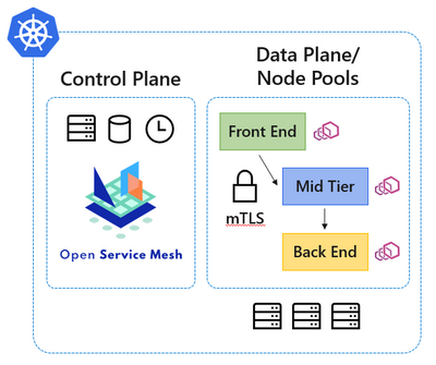
Microservice architectures have become the de facto standard for cloud native applications, and organizations are continuing to adopt, grow, and harness the Kubernetes platform for their applications’ needs. Along with the rapid volume of Kubernetes adoption comes the operational complexity to maintain and secure the vast amounts of application endpoints in these cloud native environments.
Since our initial announcement of Open Service Mesh (OSM) as an open-source community-led project back in August 2020, and later being accepted to the Cloud Native Computing Foundation (CNCF) as a sandbox project in September 2020, the core principles that inspired the project continue to ring true. Those core principles were to develop a cloud native service mesh that is simple to understand and contribute to; effortless to install, maintain, and operate; painless to troubleshoot; and finally keep OSM easy to configure via the Service Mesh Interface (SMI) specification. We are thankful to the community and all the individuals, contributors, and maintainers for their hard work in keeping the core principles at the forefront of the project.
In our efforts to provide a simplified service mesh experience for securing your cloud native application communications and endpoints, today we are excited to announce the public preview of the Open Service Mesh (OSM) Azure Kubernetes Service (AKS) add-on. Azure customers will benefit now by being able to experience first-class Azure support on a fully integrated cloud native application stack provided with AKS.
OSM is being developed as an open-source project with the CNCF, and as the project continues to mature, those enhancements will continue to inform the OSM AKS add-on. This working model with the open-source community not only allows us to rapidly develop features, but also allows us to work closely with the community in prioritizing the experiences and functionality expected by end users. We look forward to your experiences with the OSM AKS add-on.
If you are ready to get started with the public preview of the OSM AKS add-on, please visit our documentation at https://docs.microsoft.com/azure/aks/servicemesh-osm-about , which will provide more information about how to get started with the add-on for your AKS environment. We look forward to hearing about your experiences with the OSM AKS add-on.

by Scott Muniz | Mar 31, 2021 | Security, Technology
This article is contributed. See the original author and article here.
Official websites use .gov
A .gov website belongs to an official government organization in the United States.

Secure .gov websites use HTTPS A
lock ( )
) or
https:// means you’ve safely connected to the .gov website. Share sensitive information only on official, secure websites.
by Scott Muniz | Mar 31, 2021 | Security, Technology
This article is contributed. See the original author and article here.
Official websites use .gov
A .gov website belongs to an official government organization in the United States.
Secure .gov websites use HTTPS A
lock () or
https:// means you’ve safely connected to the .gov website. Share sensitive information only on official, secure websites.
by Contributed | Mar 31, 2021 | Technology
This article is contributed. See the original author and article here.
In the year 2020, Microsoft added a new capability to the Image Viewer Web part Resize and Crop. These are excellent features, but I want to try to give the End User more Manipulation Options. I was thinking about Flip and Rotate. First, I tried with CSS it worked, but for me, an Image-Editor should work in every combination of applied manipulations.
So, I started to play with canvas.
How HTML canvas works


The next step is to draw an image to our HTML canvas
<canvas id="myCanvas" width="200" height="100" style="border:1px solid #d3d3d3;"></canvas>
<script>
  const img= new Image()
  img.crossOrigin = "Anonymous";
  img.addEventListener("load", imageReceived, false);
  img.src='https://pnp.github.io/images/hero-parker-p-800.png';

  function imageReceived() {
  const c = document.getElementById("myCanvas");
  const ctx = c.getContext("2d");
  c.width = img.width;
  c.height = img.height;
  ctx.drawImage(img, 0, 0);
  ctx.font = "30px Arial";
  ctx.strokeText("Hello PnP-Community",10,50);
}
</script>
 Parker draw on canvas
How to Flip such thing
FlipY
ctx.translate(c.width, 0);
ctx.scale(-1, 1);
 Flip Parker Y
FlipX
ctx.translate(0, c.height);
ctx.scale(1, -1);
 Flip Parker X
Rotate:
To explain rotation, I start with a straightforward Sample
I draw only a Rectangle on a canvas

Then I rotate this thing for 20 Degree

As you can see the rotation Point is not in the Center of the Canvas. The Rotation Point is at Position 0,0

For this sample I want to rotate the Rectange from the center of the Black box. So we have to move center to position 0,0 than the rotation and than move it back to original position.
Now it looks good, but the edges are out of the canvas. Due to the rotation, the height and width has to be changed. Welcome back to maths class.
To i Combine the previous knowledge with the basic Parker Sample here it is
const img= new Image()
  img.crossOrigin = "Anonymous";
  img.addEventListener("load", imageReceived, false);
  img.src='https://pnp.github.io/images/hero-parker-p-800.png';

  function imageReceived() {
  const c = document.getElementById("myCanvas");
  const ctx = c.getContext("2d");
  const oldwidth =c.width = img.width;
  const oldheight =c.height = img.height;
  const degree=20;
  const radian=degree*Math.PI/180 //Radian

  const a = oldwidth * Math.abs(Math.cos(radian));
  const b =  oldheight * Math.abs(Math.sin(radian));
  const p = oldwidth * Math.abs(Math.sin(radian));
  const q =  oldheight * Math.abs(Math.cos(radian));
  const newwidth = a + b;
  const newheight = p + q;

   const offsetwidth = (newwidth - oldwidth) / 2;
   const offsetheight = (newheight - oldheight) / 2;
    c.width = newwidth;
    c.height = newheight;

  ctx.translate(newwidth/2,newheight/2);
  ctx.rotate(radian);
  ctx.translate(-newwidth/2,-newheight/2);

  ctx.fillStyle = "#0078d4";
  ctx.fillRect(offsetwidth,offsetheight,oldwidth,oldheight);

  ctx.drawImage(img, offsetwidth, offsetheight);
   ctx.font = "30px Arial";
  ctx.strokeText("Hello PnP-Community",offsetwidth+10,offsetheight+50);

}

Thank’s, Parker to be my Top-Model
Try it sp-dev-fx-webparts/samples/react-image-editor at master · pnp/sp-dev-fx-webparts (github.com)
by Contributed | Mar 31, 2021 | Technology
This article is contributed. See the original author and article here.
Educators around the world love using Whiteboard.Chat to draw, share and collaborate. They also love the ability to watch student learning and progress in real-time. Over the past few months, we have heard many requests to integrate Whiteboard.Chat with both the Immersive Reader, as well as OneNote and today we are excited to announce two new integrations.
Immersive Reader in Whiteboard.chat
Make content more inclusive is what Immersive Reader is best at, and now you can launch the Immersive Reader directly from different text types in Whiteboard.Chat elements. As you see in the video below , you can even launch the Immersive Reader from an embedded PDF in Whiteboard.Chat! This integration is now available worldwide and students can use it today.
Embed a Whiteboard.Chat into OneNote
The OneNote binder metaphor, and the ability to easily distribute Whiteboard.Chat pages in OneNote, organize them, or distribute to others in OneNote Class Notebook, seemed like a great match. Today we are excited to announce the integration between Whiteboard.Chat and OneNote!
You can now paste the URL of any Whiteboard.Chat board onto a OneNote page and it will render it as a live interactive embed, similar to how we support embedding many apps into OneNote
To see some examples or how easy this is to do in OneNote, see the example video below. This integration works in OneNote Windows 10, Online, Mac, iPad, Android. We hope to bring this to OneNote 2016 Desktop later this summer.
We hope you enjoy this new integration to bring together three great apps that educators love!
Mike Tholfsen
Microsoft Education Product Manager
@mtholfsen
by Contributed | Mar 31, 2021 | Technology
This article is contributed. See the original author and article here.
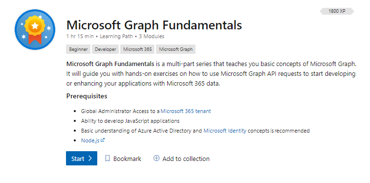
We are excited to share that we have released a new learning path on Microsoft Learn, Microsoft Graph Fundamentals, which is a multi-part series that teaches you basic concepts of Microsoft Graph. It will guide you with hands-on exercises on how to use Microsoft Graph Application Programming Interface (API) requests to start developing or enhancing your applications with Microsoft 365 data.
What is Microsoft Graph?
Microsoft Graph is the API for Microsoft 365. It is the culmination of most of the data you have in Microsoft 365, Windows 10, and Enterprise Mobility + Security all readily available to be accessed and used in your application by consuming its unified programmability model.
Why use Microsoft Graph?
Microsoft Graph helps you take advantage of a secured, unified API that can be used to connect applications to data located in various Microsoft 365 services. Developers can get started with Microsoft Graph quickly and access data across an organization without having to learn how individual Microsoft 365 services work. Security is a critical part of any organization, and Microsoft Graph helps provide built-in security to control access to various services.
Ready to get started?
Go to aka.ms/learn-graph and complete the learning path to understand the fundamentals of Microsoft Graph with lots of exercises to involve you in the learning process.
About the learning path
There are three modules that will take you on a journey through Microsoft Graph and how to use it in an application:
- In the first module, What is Microsoft Graph? you will be introduced to Microsoft Graph and basic concepts.
- In the second module, Configure a JavaScript application to retrieve Microsoft 365 data using Microsoft Graph, you will start configuring a sample JavaScript application to connect to Microsoft 365.
- In the third module, Access user photo information with Microsoft Graph, you will be able to extend the sample JavaScript application to access a user’s photo information in Microsoft 365.

Tips to successfully complete the learning path
The following are some basic prerequisites that will help you complete the Microsoft Graph learning path:
- Basic understanding of Microsoft 365.
- Basic knowledge of Representational State Transfer (REST) services and APIs.
- Ability to develop JavaScript applications.
- Basic understanding of Azure Active Directory (AAD) and Microsoft Identity concepts (preferred, but not mandatory).
For the exercises you will need:
If you are not familiar with Microsoft 365 tenants or dev tenants, we’ve got you covered! Take a look at Julie Turner’s blog, What is a Dev tenant and why would you want one?
Want to learn more about Graph? Join us for a two-hour livestream event created by developers, for developers. Let’s talk app development with Microsoft Graph!
.jpg")
Go to aka.ms/learntogether-graph and RSVP to start learning how to build apps with Microsoft Graph and connect with our developer community!
by Contributed | Mar 31, 2021 | Technology
This article is contributed. See the original author and article here.
Today I wanted to make a “bite-sized” post to walk you through setting up Azure Sphere with Azure IoT Edge.
As a refresher, Azure Sphere will perform device authentication and attestation (described here: Azure Sphere Device Authentication and Attestation Service) and if the application has specified an Azure Sphere tenant in the application manifest’s DeviceAuthentication value, it will then receive a client authentication cert which is valid for around a day.
DeviceAuthentication
|
A string that specifies the UUID of the Azure Sphere tenant to use for device authentication.
Example: “DeviceAuthentication”: “77304f1f-9530-4157-8598-30bc1f3d66f0”
|
Why is this important? Because the goal here is to use this “high assurance” client certificate to authenticate the Azure Sphere device to the Azure IoT Edge server and pass it telemetry or other data. This ensures a secure authentication method as opposed to static hardcoded passwords.
A couple of other things to remember for this demo:
- The Azure Sphere device must be able to communicate to the internet in order to perform DAA, obtain OS updates and other AS3 service communications.
- The Azure Sphere device must also have an explicit entry in the application manifest in order to communicate with the IoT Edge server:
AllowedConnections
|
A list of DNS host names or IP addresses (IPv4) to which the application is allowed to connect. If the application uses an Azure IoT Hub, the list must include the IP address or DNS host name for the hub, typically hub-name.azure-devices.net. Port numbers and wildcard characters in names and IP addresses are not accepted.
Example: “AllowedConnections” : [ “my-hub.example.net”, “global.azure-devices-provisioning.net” ]
|
- The Azure Sphere device must be a child of the IoT Edge server
The starting point for the lab is:
- Azure Sphere
- Device is claimed to tenant
- Device is in developer mode
- Device is connected to Wi-Fi
- IoT Edge
- IoT Edge runtime is installed and IoT edge server is created for a specific IoT Hub
- Deployed the simulated temperature sensor module to test and ensure basic functionality.
With that out of the way, let’s take a look at this video for a walkthrough of basic connectivity from Azure Sphere to an IoT Edge server using the Azure Sphere device certificate!

Recent Comments