This article is contributed. See the original author and article here.
Originaly posted on Olivier’s blog: How I built my first Azure RTOS GUIX display driver (olivierbloch.com)
Developing display drivers for IoT devices (not powered by a big OS like Linux or Windows) can be tricky. You don’t get to use default PC drivers which have a dependency on Linux or Windows, displays themselves can come in some esoteric forms and resolutions considering they are adapted for embedded applications (super small, not rectangular) and the protocols used for communicating with the display controllers are often proprietary and different from one another.
Azure RTOS GUIX to the rescue!
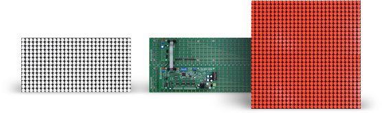
It has been some time I wanted to try Azure RTOS GUIX out as it seemed to be making developing Graphical User Interfaces (aka GUI) for embedded devices so much simpler than what I remembered from my experience as an embedded and real-time developer. I happened to have an Azure Sphere MT3620 devkit and a 28×14 Flip-Dot panel from Alfa-Zeta from a demo I inherited from my friend Mike Hall from the Azure Sphere team a couple years ago. These panels are the same as the ones you certainly have seen in airports, flipping pixels with a very satisfying click sound. It would be a shame letting this panel taking dust on a shelf or even worst in a box!
I decided to give GUIX a try to control this Flip-Dot panel doing more than just displaying some hard coded images or text. The promise of GUIX is to make the development simple while offering advanced features and functionalities AND keeping things real-time and low footprint on the embedded device. And it delivers! Here is the tale of my first-time experience with Azure RTOS GUIX.

An introduction to Azure RTOS GUIX
Azure RTOS GUIX is a high-performance, feature rich, and very small memory Graphical User Interface (GUI) middleware designed for embedded and real-time systems. It exposes APIs for anything from drawing pixels and lines to anti-aliasing, texture fills, creating and modifying screens and widgets. It also offers an event-driven programming model.
The GUIX APIs use an abstract drawing canvas in memory, which is totally independent from the hardware itself. To transfer the canvas memory to the physical display frame buffer or whatever structure is used on the hardware side, you need to write a GUIX display driver. This driver is defined by a structure containing the physical display parameters and a set of function pointers to the low-level driver functions. GUIX provides a complete, fully functional, default set of drawing functions for each supported color depth and color format. This means that in your display driver, you only have to write the code needed for hardware acceleration or other hardware specific consideration.
This means that for the simplest of drivers you only need to implement the function that initializes the hardware and eventually provide a function for toggling the canvas buffer to the physical frame one. As you’ll see below the display driver for the monochrome 28×14 Flip-Dot panel is pretty straightforward!

I invite you to learn more about the benefits of using GUIX for your real-time and embedded user interfaces by reading the docs.
In a nutshell, GUIX takes care of pretty much everything for you. To build a rich GUI for your embedded device, you only have to take care of a couple things:
- Put together a driver that will allow GUIX to control your display hardware.
- Creating a UI using concepts like windows, widgets, fonts, colors, gradients, events and more, leveraging the GUIX APIs and the desktop tool GUIX Studio
Do I need Azure RTOS ThreadX to use GUIX?
GUIX relies on a threading and tasking engine and while it is fully integrated with ThreadX, you can easily port it to other real-time OS implementing a set of elementary functions described in this documentation. Licensing is still necessary if you want to use GUIX in production even without ThreadX.
Coding my first GUIX display driver (and simple GUI to test it) for my Flip-Dot panel
Getting setup
Before I could get to the development of the display driver itself and the graphical interface using GUIX, I had to get my tools and device ready as well as create the scaffolding for the app. You can find all the detailed steps in the GitHub repo. In a nutshell, here are the things I did prior to coding the driver and the UI:
- I setup my machine and the Azure Sphere development kit
- I checked out this tutorial to learn more about running ThreadX on the Azure Sphere board
- I created a new Azure Sphere Real Time application in VS Code
- I brought in driver libraries and samples to initialize lower layers and access the MT3620 hardware resources from my ThreadX application
- Brought in Azure RTOS ThreadX and GUIX from GitHub to the project
- Created the ThreadX application files and main functions
- Wrote the few lines of code to create the GUIX thread in the ThreadX application
After I had setup the CMake config files I could test it all compiled (pretty much an empty ThreadX application starting a GUIX thread with nothing in it) I was ready for the display driver.
Writing the GUIX display driver
As described above, for a display as simple as the Flip-Dot, I didn’t have much to implement in my driver as I could rely on almost all default implementations in GUIX. I only needed to write the setup function as well as the buffer toggle one used to map and send the canvas data to the display.
The Flip-Dot panel is controlled over a serial connection using a simple protocol that Alfa -Zeta shares when you purchase one of their panels. In the case of the 28×14 panel, which is composed of 2 trays of 28×7 pixels, it consists in sending 2 frames: one for the top tray with 7 lines, and a second one for the lower tray with 7 lines. Each frame should contain the following data structure:
| # bytes | Value | Description |
|---|---|---|
| 1 | 0x80 | Frame start byte |
| 1 | 0x83 | Command byte (0x83=send to display) |
| 1 | 0x00 or 0x01 | Address (indicating which tray to send data to) |
| 28 | [Pixels data] | Data to be sent to display |
| 1 | 0x8F | Frame end byte |
For the way the pixels data is formatted, I invite you to check out the code below in the display driver used to map from the GUIX canvas to the physical one.
I created the 2 following files in my project for the driver: flipdot_graphics_driver_setup.h and flipdot_graphics_driver_setup.c
In the header file I only needed to include the GUIX api and default display driver headers, and declare the setup function:
#include "gx_api.h"
#include "gx_display.h"

UINT flipdot_graphics_driver_setup(GX_DISPLAY *display);
In the flipdot_graphics_driver_setup.c file, which is shown below, you can see the main driver setup function flipdot_graphics_driver_setup that initializes the serial port (leveraging the mt3620 library from Thinkcode Labs), sets up some local resources for managing the frame buffer mapping and then invokes the default GUIX monochrome display setup function pointing to a flipdot_buffer_toggle function meant to be invoked by GUIX when refresh of the display is needed.
The flipdot_buffer_toggle function is pretty straight forward as well, mapping the GUIX abstract canvas into the physical display buffer using map_logical_display_to_physical_display and then sending data to the Flip-Dot panel over the serial port.
The map_logical_display_to_physical_display function is not shown below as it is not really relevant for this article. In a nutshell, this function maps the content of bFlipDisp into bOutBuffer converting from the logical display format to the one expected by the Flip-Dot display controller.
#include "flipdot_graphics_driver.h"
#include "UART.h"

// Serial port stuff
#define FLIPDOT_UART MT3620_UNIT_ISU0
UART *driver = NULL;

// Flipdot hardware stuff
typedef struct {
unsigned char frameStart;
unsigned char command;
unsigned char address;
unsigned char data[28];
unsigned char frameEnd;
} flipFrame;

flipFrame frame;

const static unsigned char cmd_sendToDisplay = 0x83;

unsigned char bFlipDisp[56]; // the logical display buffer.
unsigned char bOutBuffer[56]; // the vertical stripe reverse horizontal flip-dot display buffer (aka format expected by FlipDot controller).

// Main buffer toggle function for the driver
static void flipdot_buffer_toggle(GX_CANVAS *canvas, GX_RECTANGLE *dirty)
{
// Copy canvas to logical diplay buffer
memcpy(bFlipDisp, canvas->gx_canvas_memory, 56);

// Map to physical display
map_logical_display_to_physical_display();

// Send to flipdot
// top display
frame.address = 0x00;
// copy the top display data.
memcpy(frame.data, bOutBuffer, 28);
// write the data
UART_Write(driver, (unsigned char*)&frame, sizeof(frame) );
tx_thread_sleep(3);

// bottom display
frame.address = 0x01;
// copy the top display data.
memcpy(frame.data, (bOutBuffer)+28, 28);
// write the data
UART_Write(driver, (unsigned char*)&frame, sizeof(frame) );
tx_thread_sleep(3);

}

// Driver setup
UINT flipdot_graphics_driver_setup(GX_DISPLAY *display)
{
// Init serial port
driver = UART_Open(FLIPDOT_UART, 57600, UART_PARITY_NONE, 1, NULL);

// Init frame buffer
memset(bFlipDisp, 0x00, 56);

// setup the basic display frame
frame.frameStart = 0x80;
frame.command = cmd_sendToDisplay;
frame.frameEnd = 0x8f;
frame.address = 0x00; // top display

// perform standard function pointer setup
_gx_display_driver_monochrome_setup(display, GX_NULL, flipdot_buffer_toggle);

return GX_SUCCESS;
}
The full display driver is 69 lines of actual code (after trimming out comments and blank lines)! And I am sure this could be even less with proper C coding skills ;).
Create the UI for my application with GUIX Studio
I could have written the rest from scratch, leveraging the GUIX APIs, creating windows, widgets and more by hand. At the end of the day, for a UI as simple as the one I wanted to build initially for the panel (2 lines of text) that wouldn’t have been too much of a hassle.
But why bother when you can use a WYSIWYG tool that generates the code for you, right?
So here I am installing the GUIX Studio tool and opening it up.
In GUIX Studio, I created a new project, configured the resolution of the GUI to 28×14 and 1bpp.
By default, I got a window widget which is the main window of the GUI. With so little real estate and with the ambition of only displaying some text for now, I decided to add a multiline text view filling the whole window. After some fine tuning, removal of borders, I entered “…” as default content for the text view widget.
But here I could see the issue with such a low resolution: the font! The default TEXT_INPUT font is 18 pixels high… which definitively wouldn’t work for me. I first thought that I would have to create my own font, but after looking around in the docs, I figured that the tool allowed to import True Type fonts.


Before leaving GUIX Studio I went back to my main window properties to set an Event Function called main_event_process which would be used for some event management on the window:

Last thing left to do was to export all the resource and specification files using the menu Project | Generate All Output Files:

That was it, my graphical user interface resources had been generated by the tool:
- flipdot_guix_resources.c and flipdot_guix_resources.h: containing the GUIX resources (font, display theme, color map,…)
- flipdot_guix_specifications.c and flipdot_guix_specifications.h: containing the specifications and functions for the GUI Widget (in my case, the main window and the text view)
For these files to be compiled with the project I just needed to add them to the CMakeLists.txt file.
Back to the threadx_app.c file to add my window and its widgets: in order to have something happening on the display besides just displaying text, I wanted to have a simple timer that would change the text every second, alternating between “Hello World” and “Hello World.” resulting in a blinking dot.
Here is what I needed to add to the file:
#include <stdbool.h>
#include "tx_api.h"
#include "gx_api.h"
#include "flipdot_guix_resources.h"
#include "flipdot_guix_specifications.h"
#include "flipdot_graphics_driver.h"

// GUIX Windows
GX_WINDOW_ROOT *root;

// Timer for ticker refresh
#define CLOCK_TIMER 20
static bool ticker_on = false;
I then edited the main GUIX thread to setup the driver and create the main window:
// GUIX main thread
VOID guix_thread_entry(ULONG thread_input)
{
GX_WINDOW_ROOT *root;

/* Initialize GUIX. */
gx_system_initialize();

/* Setup graphics-related hardware and create the display. */
gx_studio_display_configure(DISPLAY, flipdot_graphics_driver_setup, LANGUAGE_ENGLISH, DISPLAY_THEME_1, &root);

/* create the main screen */
gx_studio_named_widget_create("window", (GX_WIDGET *) root, GX_NULL);

/* Show the root window to make it visible. */
gx_widget_show(root);

/* start GUIX thread */
gx_system_start();
}
And I finally added the main_event_process function to create the timer when the main window gets created and then change the text in the text view widget each time the timer ticked:
// Main window event processing
UINT main_event_process(GX_WINDOW *wnd, GX_EVENT *event_ptr) {
switch (event_ptr->gx_event_type)
{
case GX_EVENT_SHOW:
// Start a timer to update text at regular intervals
gx_system_timer_start((GX_WIDGET *)wnd, CLOCK_TIMER, TX_TIMER_TICKS_PER_SECOND/2,TX_TIMER_TICKS_PER_SECOND/2);
// Call default event process
return gx_window_event_process(wnd, event_ptr);

case GX_EVENT_TIMER:
// If the timer id is our clock timer, change what's on the display
if (event_ptr->gx_event_payload.gx_event_timer_id == CLOCK_TIMER)
{
gx_multi_line_text_view_text_set(&window.window_text_view, ticker_on?"Hello World .":"Hello World");
ticker_on = !ticker_on;
}
break;

default:
return gx_window_event_process(wnd, event_ptr);
}
return GX_SUCCESS;
}
Now the moment of truth: hit F5 to compile, link, deploy and start the debug…

And that was it!
To create an Azure RTOS GUIX display driver and a graphical user interface for a real time embedded application, I only needed to go through a short series of pretty simple and well documented tasks. Doing this for embedded systems has never been easy. Azure RTOS GUIX does make it simple, totally abstracting the hardware and taking care of all the underlying layers. You can now focus on developing rich, responsive, intuitive, productive graphical user interfaces for your embedded and real-time systems!
I am sure you’ll see this panel again soon in some other projects/demos on this very blog! Stay tuned on Twitter @obloch.
The video version
I put together a little video that walks through all the steps from scratch
Try it out for yourselves (even if you don’t have a Flip-Dot panel)
Azure RTOS GUIX really makes things easy, but don’t just take my word for it and check it out for yourselves: I put the detailed steps on GitHub.

Brought to you by Dr. Ware, Microsoft Office 365 Silver Partner, Charleston SC.

Recent Comments