by Contributed | Mar 19, 2021 | Technology
This article is contributed. See the original author and article here.
This is the third blog in our series on using BitLocker with Microsoft Endpoint Manager – Microsoft Intune. In the last post, we described how to effectively troubleshoot common scenarios using the Microsoft encryption report in the Microsoft Endpoint Manager admin center. Now we’ll look at common issues, the logs and data you need to collect, and the steps you can take to troubleshoot BitLocker encryption on the client side.
BitLocker encryption process
The following steps describe the flow of events that should result in a successful encryption of a Windows 10 device that has not been previously encrypted with BitLocker:
- An administrator configures a BitLocker policy configured through Endpoint security > Disk encryption with the desired settings and targets a user group or device group.
- The policy is saved to a tenant in the Intune service.
- A Windows 10 Mobile Device Management (MDM) client syncs with the Intune service and processes the BitLocker policy settings.
- The BitLocker MDM policy Refresh scheduled task runs on the device that replicates the BitLocker policy settings to full volume encryption (FVE) registry key.
- BitLocker encryption is initiated on the drives.
The encryption report identifies common troubleshooting scenarios that are documented in the BitLocker configuration service provider (CSP) status node. However, some status scenarios might not be reported and you will need access to the device to investigate further.
There is already extensive documentation available for troubleshooting BitLocker encryption policies. You can check out Intune troubleshooting tips or follow guidelines from a Windows perspective to help isolate issues when enabling BitLocker using Intune.
Gathering data from Windows 10 devices
If you determine that there is no actionable information in the encryption report to understand why BitLocker was not enabled, the next step is to access an affected device and gather the required data to complete the investigation.
If a device is accessible, you can initiate a sync with the Intune service manually from your Windows device by selecting Settings > Accounts> Access work or school > Connect <tenant> Azure AD > Info before collecting the data.
Event logs
Mobile device management (MDM) agent event log
The MDM event log is useful to determine if there’s been an issue processing the policy sent from Intune. The OMA DM agent will connect to the Intune service and attempt to process the policies targeted at the user or device. Success and failures processing Intune policies will be found in this log.
Once the sync is complete, collect or review the following information:
LOG > DeviceManagement-Enterprise-Diagnostics-Provider admin
- Location: Right-click on Start Menu > Event Viewer > Applications and Service Logs > Microsoft > Windows > Microsoft-Windows-DeviceManagement-Enterprise-Diagnostics-Provider > Admin
- File system location: C:WindowsSystem32winevtLogsMicrosoft-Windows-DeviceManagement-Enterprise-Diagnostics-Provider%4Admin.evtx
To filter this log, right–click the event log and select Filter Current Log > Critical/Error/Warning. Then search through the filtered logs for BitLocker (press F3 and enter the text).
Errors in BitLocker settings will follow the format of the BitLocker CSP, so you will see entries like this:
./Device/Vendor/MSFT/BitLocker/RequireDeviceEncryption
or
./Vendor/MSFT/BitLocker/ConfigureRecoveryPasswordRotation
Note
You can also enable debug logging for this event log using the Event Viewer for .
BitLocker-API management event log
This is the main event log for BitLocker. If the policy has been processed by the MDM agent and there are no errors in the DeviceManagement-Enterprise-Diagnostics-Provider admin event log, this is the next log to investigate.
LOG > BitLocker-API management
- Location: Right-click on Start Menu > Event Viewer > Applications and Service Logs > Microsoft > Windows > BitLocker-API
- File system location: C:WindowsSystem32winevtLogsMicrosoft-Windows-BitLocker%4BitLocker Management.evtx
Usually, errors are logged here if there are hardware or software prerequisites missing that the policy requires such as Trusted Platform Module (TPM) or Windows Recovery Environment (WinRE). As you can see in the following example, conflicting policy settings that cannot be implemented during silent encryption and manifest as group policy conflicts are also logged:
Failed to enable Silent Encryption.
Error: BitLocker Encryption cannot be applied to this drive because of conflicting Group Policy settings. When write access to drives not protected by BitLocker is denied, the use of a USB startup key cannot be required. Please have your system administrator resolve these policy conflicts before attempting to enable BitLocker.
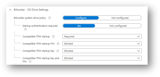
Resolution: Configuring the compatible TPM startup PIN to Blocked will resolve conflicting Group Policy settings when using silent encryption.
Configuring the TPM startup PIN and startup key to Allowed and other startup key and PIN setting to Blocked for user interaction and will result in a conflicting Group Policy error in BitLocker-AP event log.
Also, if you configure TPM startup PIN or startup key to require user interaction, it will cause silent encryption to fail. You must set the PIN and TPM startup key to Blocked if silent encryption is required.
Configuring any of the compatible TPM settings to Required will cause silent encryption to fail.
Microsoft Endpoint Manager – BitLocker | OS Drive Settings
TPM not available
Another common error in the BitLocker-API log is that the TPM is not available. The following example shows that TPM is a requirement for silent encryption:
Failed to enable Silent Encryption. TPM is not available
Error: A compatible Trusted Platform Module (TPM) Security Device cannot be found on this computer.
Resolution: Ensure there is a TPM available on the device and if it is present check the status via TPM.msc or the PowerShell cmdlet get-tpm.
Un-Allowed DMA capable bus
If the BitLocker-API log displays the status: Un-Allowed DMA capable bus/device(s) detected, it means that Windows has detected an attached Direct memory access (DMA)-capable device that might expose a DMA threat.
Resolution: To remediate this issue, first verify that the device has no external DMA ports with the original equipment manufacturer (OEM). these steps to add the device to the allowed list. Note: Only add a DMA device to the allowed list if it is an internal DMA interface/bus.
System event log
If you’re having hardware–related issues—such as problems with the TPM—errors will appear in the system event log for TPM from the TPMProvisioningService or TPM-WMI source.
LOG > System event
- Location: Right-click on Start Menu > Event Viewer > Windows Logs > System
- File system location: C:WindowsSystem32winevtLogsSystem.evtx
 Filtering properties for the System event log
Filter on these event sources to help identify any hardware-related issues that the device may be experiencing with the TPM and check with the OEM manufacturer whether there are any firmware updates available.
Task scheduler operational event log
The task scheduler operational event log is useful for troubleshooting scenarios where the policy has been received from Intune, but BitLocker encryption has not successfully initiated. BitLocker MDM policy refresh is a scheduled task that should run successfully when the MDM agent syncs with the Intune service.
The log is worth investigating when:
The BitLocker policy appears in the DeviceManagement-Enterprise-Diagnostics-Provider admin event log, in MDM diagnostics, and the registry.
There are no errors (i.e., the policy has been picked up successfully from Intune).
Nothing is logged in the BitLocker-API event log to show that encryption was even attempted.
LOG > Task scheduler operational event
- Location: Event Viewer > Applications and Service Logs > Microsoft > Windows > TaskScheduler
- File system location: C:WindowsSystem32winevtLogsMicrosoft-Windows-TaskScheduler%4Operational.evtx
Important
You must manually enable this event log before logging anything because the log will identify any problems running the BitLocker MDM policy Refresh scheduled task.
- To enable this log, Right-click on Start Menu > Event Viewer> Applications and Services > Microsoft > Windows > TaskScheduler >Operational.
 Screenshot of the TaskScheduler – Operational Logs
- Then enter task scheduler in the Windows search box, select Task Scheduler > Microsoft > Windows > BitLocker. Right-click on BitLocker MDM policy Refresh and choose Run.
When the run is complete, inspect the Last Run Result column for any error codes and examine the task schedule event log for errors.
 Example screenshot of BitLocker tasks in Task Scheduler
In the example above, 0x0 has run successfully. The error 0x41303 this means the task has never previously run.
Note
Check out this article for more information about Task Scheduler error messages.
Checking BitLocker settings
MDM Diagnostics Report
diagnose enrollment or device management issues in Windows 10 devices managed by Intune. The MDM Diagnostic Report contains useful information about an Intune enrolled device and the policies deployed to it.
The operating system (OS) build and edition in encryption failures: It’s important to investigate the OS build and edition because some CSPs were introduced on specific versions of Windows and will only work on a certain edition. For example, the bulk of BitLocker CSP settings were introduced in Windows 10, version 1703 but these settings weren’t supported on Windows 10 Pro until Windows 10, version 1809.
Additionally, there are settings such as AllowStandardUserEncryption (added in version 1809), ConfigureRecoveryPasswordRotation (added in version 1909), RotateRecoveryPasswords (added in version 1909), and Status (added in version 1903).
Checking if your Windows version and edition supports the settings configured in your policy is the first step in understanding why they are not applying correctly.
Investigating with the EntDMID: This is a unique device ID for Intune enrollment. You can use the EntDMID to search through the All Devices view in the Microsoft Endpoint Manager admin center to identify a specific device. It is also a crucial piece of information for Microsoft support to enable further troubleshooting on the service side if a support case is required.
You can also use the MDM Diagnostic Report to identify whether a policy has been successfully sent to the device with the settings the administrator configured. By using the BitLocker CSP as a reference, you can decipher which settings have been picked up when syncing with the Intune service. This article discusses this topic in more detail. You can use the report to determine if the policy is targeting the device and identify what settings have been configured using the .
MSINFO32
MSINFO32 is an information tool that contains device data you can use to determine if a device satisfies BitLocker prerequisites. The required prerequisites will depend on BitLocker policy settings and the required outcome. For example, silent encryption for TPM 2.0 requires a TPM and Unified Extensible Firmware Interface (UEFI).
- Location: In the Search box, enter msinfo32, right-click System Information in the search results and select Run as administrator.
- File system location: C:WindowsSystem32Msinfo32.exe.
However, if this item doesn’t meet the prerequisites, it doesn’t necessarily mean that you can’t encrypt the device using an Intune policy.
If you have configured the BitLocker policy to encrypt silently and the device is using TPM 2.0, it is important to verify that BIOS mode is UEFI. If the TPM is 1.2, then having the BIOS mode in UEFI is not a requirement.
Secure boot, DMA protection, and PCR7 configuration are not required for silent encryption but might be highlighted in Device Encryption Support. This is to ensure support for automatic encryption.
BitLocker policies that are configured to not require a TPM and have user interaction rather than encrypt silently will also not have prerequisites to check in MSINFO32.
TPM.MSC file
TPM.msc is a Microsoft Management Console (MMC) –in file. You can use TPM.msc to determine whether your device has a TPM, to identity the version, and whether it is ready for use.
- Location: In the Search box enter, tpm.msc, right-click and select Run as administrator.
- File system location: MMC Snap-in C:WindowsSystem32mmc.exe.
As we discussed in previous blogs, having a TPM is not a prerequisite for BitLocker but is highly recommended due to the increased security it provides.
Having a TPM is required for silent and automatic encryption. If you’re trying to encrypt silently with Intune and there are TPM errors in the BitLocker-API and system event logs, TPM.msc will help you understand the problem.
The following example shows a healthy TPM 2.0 status. Note the specification version 2.0 in the bottom right and that the status is ready for use.
 Example screenshot of a healthy TPM 2.0 status in the Trusted Platform Module console
This example shows an unhealthy status when the TPM is disabled in the BIOS:
 Example screenshot of an unhealthy TPM 2.0 status in the Trusted Platform Module console
Configuring a policy to require a TPM and expecting BitLocker to encrypt when the TPM is missing or unhealthy is one of the most common issues.
Get-Tpm cmdlet
A cmdlet is a lightweight command in the Windows PowerShell environment. In addition to running TPM.msc, you can verify the TPM using the Get-Tpm cmdlet. You will need to run this cmdlet with administrator rights.
- Location: In the Search box enter cmd, right-click and select Run as administrator > PowerShell > get-tpm.
 Example screenshot of a present and active TPM in a PowerShell window
In the example above, you can see that the TPM is present and active in the PowerShell window. The values equal True. If the values were set to False, it would indicate a problem with the TPM. BitLocker will not be able to use the TPM until it is present, ready, enabled, activated, and owned.
Manage-bde command-line tool
Manage-bde is a BitLocker encryption command line tool included in Windows. It’s designed to help with administration after BitLocker is enabled.
- Location: In the Search box, enter cmd, right–click and select Run as administrator > enter manage–bde –status.
- File system location: C:WindowsSystem32manage-bde.exe.
 Example screenshot of the manage-bde.exe command in a Command Prompt window
You can use manage-bde to discover the following information about a device:
- Is it encrypted? If reporting in the Microsoft Endpoint Manager admin center indicates a device is not encrypted, this command line tool can identify the encryption status.
- Which encryption method has been used? You can compare information from the tool to the encryption method in the policy to make sure they match. For example, if the Intune policy is configured to XTS-AES 256-bit and the device is encrypted using XTS-AES 128-bit, this will result in errors in Microsoft Endpoint Manager admin center policy reporting.
- What specific protectors are being used? There are several combination of protectors. Knowing which protector is used on a device will help you understand if the policy has been applied correctly.
In the following example, the device is not encrypted:
 Example screenshot of a device not encrypted with BitLocker
BitLocker registry locations
This is the first place in the registry to look when you want to decipher the policy settings picked up by Intune.
- Location: Right click on Start > RUN > enter regedit to open the Registry Editor.
- Default file system location:
ComputerHKEY_LOCAL_MACHINESOFTWAREMicrosoftPolicyManagercurrentdeviceBitLocker
The MDM agent registry key will help you identify the Globally Unique Identifier (GUID) in the PolicyManager that contains the actual BitLocker policy settings.
 BitLocker registry location in the Registry Editor
The GUID is highlighted in the above example. You can include the GUID (it will be different for each tenant) in the following registry subkey to troubleshoot BitLocker policy settings:
ComputerHKEY_LOCAL_MACHINESOFTWAREMicrosoftPolicyManagerProviders<GUID>defaultDeviceBitLocker
 Screenshot of the Registry Editor displaying the BitLocker policy settings configured by the MDM agent
This report shows the BitLocker policy settings that have been picked up by the MDM agent (OMADM client). These are the same settings that you will see in the MDM Diagnostic report, so this is an alternative way of identifying settings that the client has picked up.
Example of EncryptionMethodByDriveType registry key:
<enabled/><data id="EncryptionMethodWithXtsOsDropDown_Name" value="6"/><data id="EncryptionMethodWithXtsFdvDropDown_Name" value="6"/><data id="EncryptionMethodWithXtsRdvDropDown_Name" value="3"/>
SystemDrivesRecoveryOptions:
<enabled/><data id="OSAllowDRA_Name" value="true"/><data id="OSRecoveryPasswordUsageDropDown_Name" value="2"/><data id="OSRecoveryKeyUsageDropDown_Name" value="2"/><data id="OSHideRecoveryPage_Name" value="false"/><data id="OSActiveDirectoryBackup_Name" value="true"/><data id="OSActiveDirectoryBackupDropDown_Name" value="1"/><data id="OSRequireActiveDirectoryBackup_Name" value="true"/>
BitLocker registry key
The settings in the policy provider registry key will be duplicated into the main BitLocker registry key. You can compare the settings to ensure they match what appears in the policy settings in the user interface (UI), MDM log, MDM diagnostics and the policy registry key.
This is an example of the FVE registry key:
Registry key location: ComputerHKEY_LOCAL_MACHINESOFTWAREPoliciesMicrosoftFVE
 Screenshot of the BitLocker registry keys found in the Registry Editor
- EncryptionMethodWithXtsOs, EncryptionMethodWithXtsFdv and EncryptionMethodWithXtsRdv have the following possible values:
- 3 = AES-CBC 128
- 4 = AES-CBC 256
- 6 = XTS-AES 128
- 7 = XTS-AES 256
- UseTPM, UseTPMKey, UseTPMKeyPIN, USeTPMPIN are all set to 2,which means they are all set to allow.
- Notice that most of the are divided into groups of settings for the operating system drive (OS), fixed drive (FDV) and removable drive (FDVR).
- OSActiveDirectoryBackup has a value of 1 and is enabled.
- OSHideRecoveryPage is equal to 0 and not enabled.
You can decode all of the setting names in the registry using the BitLocker CSP documentation.
REAgentC.exe command line tool
REAgentC.exe is a command line executable tool that you can use to configure the Windows Recovery Environment (Windows RE). WinRE is a prerequisite for enabling BitLocker in certain scenarios such as silent or automatic encryption.
- Location: Right-click on Start > Run > enter cmd > right–click cmd and select Run as administrator > reagnetc /info.
- File system location: C:WindowsSystem32ReAgentC.exe.
Tip
If you see error messages in the BitLocker-API about WinRe not being enabled, run the following command on the device to determine the WinRE status:
 Output of the ReAgentC.exe command in Command Prompt
If the WinRE status is disabled, it is possible to enable it manually using the following command line as an administrator:
 Example screenshot to enable ReAgentC.exe in Command Prompt
Conclusion
When BitLocker fails to enable on a Windows 10 device using an Intune policy, in most cases, the hardware or software prerequisites are not in place. Examining the BitLocker-API log will help you identify which prerequisite is not satisfied. The most common are:
- TPM is not present
- WinRE is not enabled
- UEFI BIOS is not enabled for TPM 2.0 devices
Policy misconfiguration can also cause encryption failures. Not all Windows devices can encrypt silently so think about the users and devices that you’re targeting.
Configuring a startup key or PIN for a policy intended for silent encryption will not work because of the user interaction required when enabling BitLocker. Keep this in mind when configuring the BitLocker policy in Intune.
It is useful to be able to verify whether the policy settings have been picked up by the device to determine whether the targeting has been successful.
It is possible to identify the policy settings using MDM diagnostics, registry keys and the to verify if the settings have been successfully applied. The BitLocker CSP documentation can help you decipher these settings to understand whether they match what has been configured in the policy.
There are multiple places to configure BitLocker settings in the Microsoft Endpoint Manager admin center – Security baselines, Endpoint security, and Configuration profiles. The preferred and recommended approach is to use Endpoint security > Disk encryption.
Reference
diagnostic checks, and command-line tools discussed in this post:
Logs
- DeviceManagement-Enterprise-Diagnostics-Provider admin event log: Use this log for MDM policy processing and errors applying the CSP settings.
- BitLocker-API and system event log: Investigate this log if the policy has been processed successfully and Windows is now attempting to implement the settings.
- Task scheduler operational event log: Check this log if the policy has been processed in DeviceManagement-Enterprise but nothing has happened in BitLocker-API.
- Collect diagnostics remote action: Use Intune to collect logs remotely without interrupting the user.
BitLocker settings checks
- MDM Diagnostics report: Use this report to verify if BitLocker settings have been applied and what they are configuring.
- Registry keys: Use to verify if the policy received from MDM provider has applied to Windows correctly.
Command line/Powershell tools
- Get-Tpm cmdlet: Check the TPM status of the device.
- Tpm.msc: Check the TPM status of the device.
- REAgentc.exe: Check WinRE status of the device.
- MSINFO32.exe: Check the hardware prerequisites for BitLocker.
- Manage-bde.exe: Check the BitLocker encryption status of the device.
More info and feedback
For further resources on this subject, please see the links below.
Enforcing BitLocker policies by using Intune known issues
Diagnose MDM failures in Windows 10 – Windows Client Management
BitLocker Management Recommendations for Enterprises (Windows 10)
Guidelines for troubleshooting BitLocker – Microsoft 365 Security
The next post will cover the BitLocker Recovery Key. Stay tuned! Catch up on other posts in the series:
- Enabling BitLocker with Microsoft Endpoint Manager – Microsoft Intune – Microsoft Tech Community
- Troubleshooting BitLocker from the Microsoft Endpoint Manager admin center – Microsoft Tech Community
Let us know if you have any additional questions by replying to this post or reaching out to @IntuneSuppTeam on Twitter.

by Contributed | Mar 19, 2021 | Technology
This article is contributed. See the original author and article here.
It’s 5 PM on Friday evening – the weekend will soon be here. You do one last sweep of your inbox before signing off when your cellphone the bat phone rings. Someone didn’t get the memo about the unwritten operational rule of IT Administration: Never make changes on a Friday. The phone itself seems terrified with every ring. A panicked voice on the other end says, “I can’t ping my VM.” Pandemonium ensues…
Today we’re going to talk about a new, free, downloadable tool that can help.
Networks are complex. There are many different vendors, with many different configurations – Even your network team might be different than your Server/HCI team. In the revelry mentioned above, everything may look the same on your hosts, but it’s hard to know if the issue is caused by the host or the physical network without being able to see the physical network configuration.
If LLDP is enabled on your switchports, it can be an easy task to quickly validate some of the physical network settings. LLDP or Link Layer Discovery Protocol is an IEEE standard (802.1AB) that allows networked devices to advertise their configuration (among other things) to neighboring devices. To Windows and Azure Stack HCI, the neighboring device is the physical switchport that its connected (via the NIC). LLDP’s Wikipedia site has a nice intro where you can learn a bit more.
With LLDP, switchports can advertise the VLAN, MTU, and DCB configuration among others information which can be critical information for Azure Stack HCI systems. However, not all switches support advertisement of the same information. Without getting into the details (which you can read more about on the Wikipedia site linked above), the switch will determine how much information you can view.
Azure Stack HCI Network Switches
To improve Azure Stack HCI reliability where we have a purpose-built OS, we have begun to require that switches support LLDP. Most importantly, we require that they support some of the “organizationally specific Custom TLVs.” That is a fair amount of jargon, but it boils down to supporting capabilities like VLAN, MTU, etc. In the picture below, you can see the Organizationally Specific TLVs (type 127) along with the MTU and PFC configuration of the switchport this NIC is attached.

Note: We intend to grow the list of required TLVs over time as we work with network vendors. Check the Custom TLVs documentation link just above for updates.
Help! I need to buy a switch for Azure Stack HCI!
We document some Network Switches for Azure Stack HCI that the vendor has verified meet the requirements – the list will grow as we hear from the various switch vendors. Talk to your Network Vendor to see if your switch meets the requirements.
Having this information at your disposal can help you answer several critical questions particularly when you want to get started on your weekend:
- Did you misconfigure your host or is it the physical network?
- Did the network engineer add the necessary configuration to the correct switchport?
- Is the switchport configuration the same on each team member?
- Is the switchport configuration the same between each cluster node?
Help! My Network Admin says LLDP is insecure!
LLDP does not require credentials to receive information but that doesn’t mean it’s insecure. LLDP allows the administrator of the network device to choose which information (TLVs), if any, is sent to neighbors with the intention that this information can be used for diagnostic purposes.
Get Started
Back to our IT hero for a moment. How can you quickly determine whether the issue is on the switch or you missed some settings on your host?
An LLDP enabled switchport will periodically (typically every 30 seconds) send messages to its neighbors, including the juicy information you may want as an IT Administrator to determine whether your physical host configuration matches that of the physical network.
Retrieving this information is traditionally a bit of a challenge, however there is a tool to make this simple.
Note: If you’re not in control of your network switches, make sure you ask your network team to enable LLDP and any “organizationally specific TLVs” that the switch supports.
Install the Module
First install the DataCenterBridging module from the PowerShell gallery. This module contains a few goodies and has been updated to include the functions to parse the LLDP data from the switch.

There are four available commands at the time of writing:

Getting the Physical Switch Information
Let’s start off by trying to get the LLDP information using Get-FabricInfo. With each of the commands you can specify the SET Switch or individual Interface names (using the InterfaceName parameter). In this case, we are specifying the SET Switch that starts with the name Converged. The cmdlet finds all the physical NICs attached the switch and looks for available LLDP messages on each interface.
At first run, it probably will not find anything. The cmdlet tells you to run Test-FabricInfo to help identify the problem.

Running Test-FabricInfo identifies a few problems that we need to resolve.

You can use Enable-FabricInfo to resolve all the problems in one shot. This will install the feature and ensure that the LLDP agent is enabled on the underlying interfaces, etc.

Note: Want to know everything this is doing? Look at the code on GitHub!
Next, run Test-FabricInfo again to determine if all the requirements are met. You can see we got a little better. Only two remaining issues; we didn’t find any LLDP packets for the interfaces in the SET switch.

Wait about 30 seconds – the typical amount of time that a switchport will send LLDP packets – and try again. If you still fail after the messages above, contact your network administrator and ensure that LLDP is enabled on the switchports connected to your team members.
If LLDP is enabled on your physical switch, you will see the following below which indicates that Test-FabricInfo found an LLDP message from the physical switch for each member of the Converged team.

Now we are ready to run Get-FabricInfo. Make sure you put the output into a variable, so you can inspect it. In this case, we add everything to the $FabricInfo variable which has an object for every team member.

You can walk the individual team members to see information collected on the Windows or HCI host (under InterfaceDetails) or the physical switch (Fabric) to which the NICs are connected.

For example, here’s a look at the IP and Subnet information on pNIC01. We collect this so it’s easy to compare to the information collected from the switch. As you can see, we have the IP Address, Subnet, VLAN, etc.
In this case, we have a virtual switch on the host and as part of the storage configuration on this system, we have a team mapped host vNIC. The IP, Subnet, etc. are being displayed from that team-mapped host vNIC. If the team member isn’t part of a virtual switch, we’ll display the configuration on the physical NIC.

Now let’s take a look at what the switch sent us and what we can learn about the physical network (as mentioned before, the information will vary based on what the switch supports):
- NativeVLAN: 1133 – Untagged traffic will be sent over this vlan
- VLANID: Info Not Provided… This includes the trunked VLANs that can be carried on this switchport. The switch below did not include this information in the packet sent to the host.
- FrameSize: 9236 – The physical NIC and virtual NICs MTU configuration should not exceed the switches value or traffic will be segmented (or in some cases dropped).
- PFC is enabled on Priority3 – Data needing lossless communication (e.g. RoCE-based RDMA) should use Priority 3.

From this information, we can determine that VLAN 711 (on the storage vNIC) is not using the native vlan, and the switch is not showing the trunked VLANs in LLDP either. This leads to two conclusions:
- We should check the switch configuration or contact our network administrator if network connectivity is not available on pNIC01 because we could not confirm that traffic is available here.
- We should ask our network administrator to find us a switch that does advertise this information so that we can identify this problem ourselves (and without ruining their weekend).
Here’s the same view but from another switch. This switch did not send the PFC information, but it does show the VLAN IDs available to the host (1, 11, 12, and 40).

From here, we can tell that VLAN 711 is not available on the physical network which is at least one obvious reason why there may not be network connectivity on this link.
Some of the other problems on the physical network that you can easily identify:
- Missing VLANs
- Misconfigured Jumbo Frames
- Misconfigured PFC settings
- Topology problems e.g. cabled to the wrong switch (check ChassisGroups for this information)
Reminder: The information displayed is dependent on the switch’s capabilities. If the switch is unable to provide us with a certain TLV, we display the text “Information Not Provided By Switch.” If you see this message, you should work with your network administrator to identify if the information can be included.
Summary
Get-FabricInfo allows you to answer several questions about the physical network configuration that may come in handy when troubleshooting diagnostic issues. Is the physical network setup as I expected it? Is the configuration the same between cluster nodes? All of this and more can be answered if your switch supports LLDP and you’re running Windows or Azure Stack HCI.
Hopefully that Friday afternoon call isn’t quite so scary anymore!
Thanks for reading,
Dan “weekend warrior” Cuomo
![Power Up Microsoft 365 with the Power Platform [M365 Meetup for Government]](https://www.drware.com/wp-content/uploads/2021/03/large-1330)
by Contributed | Mar 19, 2021 | Technology
This article is contributed. See the original author and article here.
Microsoft 365’s greatest business impact can be achieved using the Power Platform family of technologies. PowerApps, Power Automate, and PowerBI are a core part of the Microsoft 365 experience and empower both citizen developers and IT to meet the mission needs of the organization.
Microsoft PowerApps allow organizations to efficiently and effectively drive toward a zero trust security model within their existing budget and M365 services scope. Because MS PowerApps are a low code development framework, included with your government Microsoft 365 (M365) subscription, existing M365 Engineers can quickly adjust service delivery methods without starting from scratch or purchasing additional costly development tools or specialized Subject Matter Development Experts. In this session, we will focus on transforming enterprise IT service administration leveraging MS PowerApps, which allows for low level IT administration without risk of high level access and permissions.
Event Link:
Sign up for the event here!
Session 1: Power Platform Introduction
Presenter:
Steve Winward, Microsoft Technical Specialist
https://www.linkedin.com/in/stevewinward/
Session 2: Utilizing Power Platform to achieve a Zero Trust
 Vamonos IT LLC (link)
Presenters:
Chris Current – https://www.linkedin.com/in/chris-current-0972941b3/
Joe Tyner – https://www.linkedin.com/in/joetyner/
Jenny Bunch – https://www.linkedin.com/in/jenny-bunch/
Dave Harrison – David Harrison | LinkedIn
by Contributed | Mar 19, 2021 | Technology
This article is contributed. See the original author and article here.
The use of virtual hostnames with SAP systems is a familiar approach to SAP customers, allowing the decoupling of actual SAP Server hostnames from the hostname referred to by the SAP instance. It provides a degree of abstraction allowing for simpler virtualization, naming conventions, hardware lifecycles, organizational policies, datacenter migrations and Disaster Recovery.
This blog post will provide step-by-step instructions on how to reliably deploy an Azure VM with the actual VM Server hostname, as well as the SAP Virtual hostname on a single network interface. These instructions only apply to Windows Operating system.
NOTE: Please note that the configuration described in this article does not apply to servers using Windows Server Failover Clustering (WSFC) which can provide high availability to SAP Database and SAP Central Services servers(A/SCS.) This configuration can be applied to SAP Application Servers and 2-tier SAP systems (Application, and SCS servers installed on a single VM.)
More detail
When migrating to Microsoft Azure, many customers choose to use a single network interface for their SAP VMs, as it simplifies automation of deployments and management. A common design misconception is that multiple network interfaces increase network throughput, however in Microsoft Azure, unlike many on-premises configurations, Azure Virtual Machines can scale network bandwidth to their potential maximum for that VM size with just a single network interface. There is no need for multiple network interfaces to scale bandwidth.
As detailed in SAP Note 2109662 – Windows returns wrong IP address as source IP however, the SAP installation will throw an error unless Windows IP addresses and the DNS registration of VM hostname and the SAP Virtual hostname are configured properly.
This configuration is detailed in SAP Note 1564275 – Install SAP Systems Using Virtual Host Names on Windows, however this blog will focus on how to accomplish this specifically in Microsoft Azure.
Technical Solution
In this blog we will use the example of an SAP App server with 1 Network Interface attached and the following configuration:
- Subnet:
- Name = App
- CIDR = 10.0.0.0/26
- Netmask = 255.255.255.192
- Default Gateway (1st IP address of subnet) = 10.0.0.1
- IP address/FQDN:
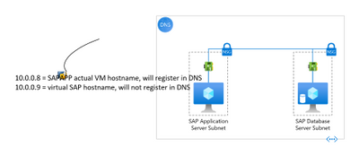
- 10.0.0.8 = sapapp.contoso.local (<- VM fully qualified domain name)
- 10.0.0.9 = sapvhost.contoso.local (<- SAP virtual fully qualified domain name)
Figure 0: A layout of what we want to achieve
First, let us look at the updates needed from the Portal.
When you are adding an additional IP configuration to the Azure NIC from Microsoft Azure portal, you can add an additional IP configuration on the Home > Network interface > “NIC Name” > IP configurations blade in the following way:

Figure 1: Open NIC configuration blade and click “Add”

Figure 2: adding second IP configuration in the add ipconfig blade
Now we move to the VM and RDP into it. The first thing you will notice once you boot-up is that, only one IP configuration is visible in the VM. The reason is that Azure DHCP, by default, assigns the primary IP configuration from the Azure NIC to the network interface within the VM. The secondary IP configurations must be manually assigned at the VM OS level.

Figure 3: Output of “ipconfig /all” on the VM
Now that we are on the VM, let us walk through the steps needed to allow us to use SAP virtual hostnames on Windows.
- Windows Servers provide a convenient capability to register each of its assigned IP addresses in DNS. This means that some of the default options allow Windows Server machines to automatically register the IP addresses of the network adapters in DNS after a server restart. To prevent this, you must unset the “Register this connection’s addresses in DNS” option for the network adapters. This setting can be found on the DNS tab of the Advanced TCP/IP Settings property window for TCP/IPv4. This is a very important step, if we do not unset the option the Windows DNS client service registers both IP addresses for the Windows host name in DNS resulting in name resolution issues.

Figure 4: Uncheck the checkbox highlighted to prevent auto registration of IP addresses.
- Make sure that the Remote registry service is enabled and running. This would be required to make changes in the registry to update the properties of the network adapters registered with DNS.
HKEY_LOCAL_MACHINESYSTEMCurrentControlSetServicesTcpipParametersDNSRegisteredAdapters{<36 character GUID corresponding to the network adapter that TCPIP was bound to>}
- Now we add the additional IP configuration on the network card
- On the “General” tab of the TCP/IPv4 properties, change the IP address acquisition to manual. This is because, as explained above, Azure DHCP only propagates the primary IP configuration to the network adapter, and we want both the IP addresses assigned to it.

Figure 5: Set the IP addresses manually
Note: If you set this properly, you will experience a short disconnection to your RDP session and connect back. If you did not set any of the properties correctly, you will not be able to connect back until the VM is rebooted.
- In the “IP Settings” tab of the advanced settings property window, you should see the manually entered IP address.

Figure 6: the primary address should show up on the “Advanced” properties window
- Add the additional IP address by clicking “Add”. The “IP settings” tab should look like below before clicking OK.

Figure 7: After adding the secondary IP configuration on the network adapter
- Next, we set “SkipAsSource” to “True” (default is “False”) for the secondary IP Address i.e., 10.0.0.9, which we added in the above step. We do this to prevent the secondary IP address from registering in DNS automatically. If “SkipAsSource” is set to “True”, then that IP address will not be registered in DNS and will not be used for host initiated outgoing communications, unless an application specifically binds to it. The preferred way to do this is via PowerShell (as shown below).
#Get interface alias, ip addresses and the skip as source before starting
Get-NetAdapter | Get-NetIPAddress | `
    Where-Object -FilterScript { $_.AddressFamily -eq "IPv4" } | `
    Select-Object InterfaceAlias, IPAddress, SkipAsSource

$primaryIP = "10.0.0.8" #replace with your primary ip
$netInterface = "Ethernet 3" #replace with your network adapter name

# get all the IP addresses on the interface, filtered by IPv4 and excluding
# the $primaryIP
[array]$IPs = Get-NetIPAddress -InterfaceAlias $netInterface | ``
    Where-Object { $_.AddressFamily -eq "IPv4" -and $_.IPAddress -ne $primaryIP }

# set primary IP SkipAsSource to false
Set-NetIPAddress -IPAddress $primaryIP -InterfaceAlias $netInterface -SkipAsSource $false

# set other IP addresses with SkipAsSource equal to true
Set-NetIPAddress -IPAddress $IPs.IPAddress -InterfaceAlias $netInterface -SkipAsSource $true

#check all properties are set properly
Get-NetAdapter | Get-NetIPAddress | `
    Where-Object -FilterScript { $_.AddressFamily -eq "IPv4" } | `
    Select-Object InterfaceAlias, IPAddress, SkipAsSource
Once we complete running the code, the output from the Get-NetAdapter command above should look like this:

Figure 8: setting “SkipAsSource” to True on the secondary IP address of the NIC
- At this point we can create the Host (A) records in DNS for the Virtual Hostnames. For the reverse lookups to work, we need to ensure the flag; “Update associated pointer (PTR) record”, is set on both the addresses.

Figure 9: Host (A) records in DNS for the server and virtual hostnames

Figure 10: setting to update the PTR records in DNS
- On the VM, we need to notify Windows that the Virtual Hostname being used is actually an alternate name for the computer. We do this by adding a new multi-string value ‘BackConnectionHostnames’ under the “HKEY_LOCAL_MACHINESYSTEMCurrentControlSetControlLsaMSV1_0” key. You can use the below PowerShell for doing this, change the sapvhost and sapvhost.contoso.local to the virtual hostnames’ short-name and FQDN.
New-ItemProperty -Path 'HKLM:SystemCurrentControlSetControlLsaMSV1_0' `
                 -Name "BackConnectionHostNames" `
                 -Value "sapvhost","sapvhost.contoso.local" `
                 -PropertyType MultiString
Note: This setting would not need a server restart to work. You can complete all the steps and reboot the machine
- Now that we have notified Windows that the machine has alternate names, we need to also tell Windows to allow inbound connections which are directed to this Virtual Hostname. We do this by adding a DWord value called ‘DisableStrictNameChecking’ under the key “HKEY_LOCAL_MACHINESYSTEMCurrentControlSetServiceslanmanserverparameters”
New-ItemProperty -Path 'HKLM:SYSTEMCurrentControlSetServiceslanmanserverparameters' `
                 -Name "DisableStrictNameChecking" `
                 -Value "1" `
                 -PropertyType DWord
- At this point, we can reboot the VM.
- Once the VM is back online, we can log back in and do some validations
- Let us check if the ipconfig shows both the IP Addresses. We can do this after adding the second IP on the NIC as well.

Figure 11: validating that the second IP shows up in ‘ipconfig /all’ command
- Validate that reverse lookup works for the secondary IP

Figure 12: validating that reverse lookup works for secondary IP
- Check that the DisableStrictNameChecking and BackConnectionHostnames settings are working by running “net view virtualhostname” and browsing to the virtual hostname through the command prompt. Ideally, run these from a different machine to check further.

Figure 13: checking the shares are available by running net view command
- Another good test is to open the Computer Management MMC and open the virtual hostname from Action -> Connect to Another Computer -> virtual host name. If you can browse the ‘Local Users and Groups’ and ‘Services and Applications’, it is a good sign and SAPinst should be successful.

Figure 14: Test connecting to SAP virtual hostname from MMC
- Once all the tests from above tests have succeeded, we can start with the SAP installation using the virtual hostname now by running SAPinst from an administrative command prompt and execute the following command: SAPinst.exe SAPINST_USE_HOSTNAME=<virtualname>.
Summary
To recap the configuration above, here are the 6 basic steps required on the Windows virtual machine to prep it for SAP installation using virtual hostnames with a single network interface:
- Uncheck the “Register this connection’s addresses in DNS” setting on the primary NIC
- Add a second IP address configuration through the Azure Portal, and then within the VM add the second IP address to the Network Interface’s IPv4 properties
- Follow SAP Note 2109662 – using PowerShell set the “SkipAsSource” property on the second IP address (desired outcome: first IP address à SkipAsSource=false; secondary/virtual IP address à SkipAsSource=true)

Figure 15: After setting SkipAsSource, the interface details
- 10.0.0.8 = actual VM hostname, will automatically register in DNS
- 10.0.0.9 = virtual SAP hostname, will not automatically register in DNS, we will manually create this DNS record
- Maintain the registry entries:
- HKEY_LOCAL_MACHINESYSTEMCurrentControlSetServiceslanmanserverparametersDisableStrictNameChecking = 1 (Type: DWORD)
- HKEY_LOCAL_MACHINESYSTEMCurrentControlSetControlLsaMSV1_0BackConnectionHostnames = FQDN short hostname (Type: Multi-string value)
(ex: sapvhost.contoso.local sapvhost <Not a space, but a carriage return between these>)
- Re-set the “Register this connection’s addresses in DNS” setting on the primary NIC
- Outcome:
- VM Primary IP Address (10.0.0.8) will register in DNS with actual VM hostname
- You must manually create an A-record for the VM secondary IP Address 10.0.0.9 and the virtual SAP Hostname
To ensure you have completed these steps correctly you can validate the configuration by:
- DNS forward lookup (e.g., “nslookup sapvhost.contoso.local”)
- DNS reverse lookup (e.g., “nslookup 10.0.0.9”)
- Browse to the sapvhost.contoso.local UNC address through either the command prompt or File Explorer.
After executing this set of steps on your VM, you are now prepared to start the SAP installation by starting SAPinst on the VM using virtual hostnames. Start SAPinst from an administrative command prompt and execute the following case-sensitive command: SAPinst.exe SAPINST_USE_HOSTNAME=<virtualhostname>.
References

by Contributed | Mar 19, 2021 | Technology
This article is contributed. See the original author and article here.
By Eric Horvitz, Chief Scientific Officer
It’s that time of year when computer science educators from across the world come together to exchange ideas at the ACM SIGCSE Technical Symposium. With the accelerating sophistication and influence of computing technologies comes a critical need: Computer science education. The work of computer science educators is essential in educating and inspiring our up-and-coming computer scientists.
It’s inspiring to see the innovative ways that the teaching of computer science is evolving. And it’s heartening to see the soaring popularity of computer science. Computer science is now considered a noble profession, much like medicine and law have been viewed over the decades. Record numbers of college students are choosing computer science as their major.
Beyond serving as a path to a career in computer science, CS education provides key pathways into professions like biomedicine, aerospace, chemistry, physics, and the social sciences—places where computing is not peripheral, but where it has become a central part of the disciplines.
With great power and influence, comes great responsibility. Today, computing advancements are framing hard questions about the influence of computing technologies on people and society, including issues around safety, privacy, civil liberties, civil rights, access to technology, and the fairness of systems. Important questions have come to the fore about the outsized influence of computing technologies on our patterns of our attention, on the information that we consume, and how we spend our time. These questions and issues are growing to become an important part of computer science education. It’s wonderful to see CS educators developing and including formal content on values, ethics, and responsibilities.
All of us can remember that moment in our life when an inner voice whispered: This is what I like doing! This is who I am. This is who I will be. Educators play such a central role for students on this path of discovery. They are not only the source of knowledge—they are the source of students’ self-knowledge, the spiritual guides behind the rising spirits. Educators play such an important role with clarity and creativity with teaching, including insightful artistry with the sequencing of concepts via curricula.
From all of us at Microsoft, I’d like to extend a huge thank you! to computer science educators across the world. Thank you for the magic you bring to the classrooms, the engaging ideas, and the way you motivate, encourage, and excite computer science students.
(From opening remarks at SIGCSE Technical Symposium)

Recent Comments