Configuring a GlusterFS using Azure Shared Disks on Ubuntu Linux

Configuring a GlusterFS using Azure Shared Disks on Ubuntu Linux

This article is contributed. See the original author and article here.

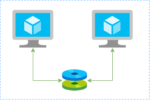
In this article I’ll show you how to create a redundtant storage pool using GlusterFS and Azure Shared Disks. GlusterFS is a network-attached storage filesystem that allows you to pool storage resources of multiple machines. Azure shared disks is a new feature for Azure managed disks that allows you to attach a managed disk to multiple virtual machines (VMs) simultaneously. Please note that enabling shared disks is only available to a subset of disk types. Currently only ultra disks and premium SSDs can enable shared disks. Check if the VM type you are planning to use support ultra or premium disks.


glusterfs.png


Our setup will consist in:


  • An Azure Resource Group containing the resources

    • An Azure VNET and a Subnet

    • An Availability Set into a Proximity Placement Group

    • 2 Linux VMs (Ubuntu 18.04)

      • 2 Public IPs (one for each VM)

      • 2 Network Security Groups (1 per VM Network Interface Card)


    • A Shared Data Disk attached to the both VMs


I’ll be using the Azure Cloud Shell once is fully integrated to Azure and with all modules I need already installed.


Create SSH key pair


ssh-keygen -t rsa -b 4096


Create a resource group


New-AzResourceGroup -Name “myResourceGroup” -Location “EastUS”


Create virtual network resources


Create a subnet configuration


$subnetConfig = New-AzVirtualNetworkSubnetConfig `
-Name “mySubnet” `
-AddressPrefix 192.168.1.0/24


Create a virtual network


$vnet = New-AzVirtualNetwork `
-ResourceGroupName “myResourceGroup” `
-Location “EastUS” `
-Name “myVNET” `
-AddressPrefix 192.168.0.0/16 `
-Subnet $subnetConfig


Create a public IP address for the VM01


$pip01 = New-AzPublicIpAddress `
-ResourceGroupName “myResourceGroup” `
-Location “EastUS” `
-AllocationMethod Static `
-IdleTimeoutInMinutes 4 `
-Name “mypublicip01”


Create a public IP address for the VM02


$pip02 = New-AzPublicIpAddress `
-ResourceGroupName “myResourceGroup” `
-Location “EastUS” `
-AllocationMethod Static `
-IdleTimeoutInMinutes 4 `
-Name “mypublicip02”


Create an inbound network security group rule for port 22


$nsgRuleSSH = New-AzNetworkSecurityRuleConfig `
-Name “myNetworkSecurityGroupRuleSSH” `
-Protocol “Tcp” `
-Direction “Inbound” `
-Priority 1000 `
-SourceAddressPrefix * `
-SourcePortRange * `
-DestinationAddressPrefix * `
-DestinationPortRange 22 `
-Access “Allow”


Create a network security group for the VM01


$nsg = New-AzNetworkSecurityGroup `
-ResourceGroupName “myResourceGroup” `
-Location “EastUS” `
-Name “myNetworkSecurityGroup01” `
-SecurityRules $nsgRuleSSH


Create a network security group for the VM02


$nsg = New-AzNetworkSecurityGroup `
-ResourceGroupName “myResourceGroup” `
-Location “EastUS” `
-Name “myNetworkSecurityGroup02” `
-SecurityRules $nsgRuleSSH


Create a virtual network card for VM01 and associate with public IP address and NSG


$nic01 = New-AzNetworkInterface `
-Name “myNic01” `
-ResourceGroupName “myResourceGroup” `
-Location “EastUS” `
-SubnetId $vnet.Subnets[0].Id `
-PublicIpAddressId $pip01.Id `
-NetworkSecurityGroupId $nsg.Id


Create a virtual network card for VM02 and associate with public IP address and NSG


$nic02 = New-AzNetworkInterface `
-Name “myNic02” `
-ResourceGroupName “myResourceGroup” `
-Location “EastUS” `
-SubnetId $vnet.Subnets[0].Id `
-PublicIpAddressId $pip02.Id `
-NetworkSecurityGroupId $nsg.Id


Create availability set for the virtual machines.


$set = @{
Name = ‘myAvSet’
ResourceGroupName = ‘myResourceGroup’
Location = ‘eastus’
Sku = ‘Aligned’
PlatformFaultDomainCount = ‘2’
PlatformUpdateDomainCount = ‘2’
}
$avs = New-AzAvailabilitySet @set


Create the first virtual machine (myVM01)


Define a credential object


$securePassword = ConvertTo-SecureString ‘ ‘ -AsPlainText -Force
$cred = New-Object System.Management.Automation.PSCredential (“azureuser”, $securePassword)


Create a virtual machine configuration


$vmConfig = New-AzVMConfig `
-AvailabilitySetId $avs.Id `
-VMName “myVM01” `
-VMSize “Standard_D4s_v3” | `
Set-AzVMOperatingSystem `
-Linux `
-ComputerName “myVM01” `
-Credential $cred `
-DisablePasswordAuthentication | `
Set-AzVMSourceImage `
-PublisherName “Canonical” `
-Offer “UbuntuServer” `
-Skus “18.04-LTS” `
-Version “latest” | `
Add-AzVMNetworkInterface `
-Id $nic01.Id


Configure the SSH key


$sshPublicKey = cat ~/.ssh/id_rsa.pub
Add-AzVMSshPublicKey `
-VM $vmconfig `
-KeyData $sshPublicKey `
-Path “/home/azureuser/.ssh/authorized_keys”


Create the VM


New-AzVM `
-ResourceGroupName “myResourceGroup” `
-Location eastus -VM $vmConfig


Create the second virtual machine (myVM02)


Define a credential object


$securePassword = ConvertTo-SecureString ‘ ‘ -AsPlainText -Force
$cred = New-Object System.Management.Automation.PSCredential (“azureuser”, $securePassword)


Create a virtual machine configuration


$vmConfig = New-AzVMConfig `
-AvailabilitySetId $avs.Id `
-VMName “myVM02” `
-VMSize “Standard_D4s_v3” | `
Set-AzVMOperatingSystem `
-Linux `
-ComputerName “myVM02” `
-Credential $cred `
-DisablePasswordAuthentication | `
Set-AzVMSourceImage `
-PublisherName “Canonical” `
-Offer “UbuntuServer” `
-Skus “18.04-LTS” `
-Version “latest” | `
Add-AzVMNetworkInterface `
-Id $nic02.Id


Configure the SSH key


$sshPublicKey = cat ~/.ssh/id_rsa.pub
Add-AzVMSshPublicKey `
-VM $vmconfig `
-KeyData $sshPublicKey `
-Path “/home/azureuser/.ssh/authorized_keys”


Create the VM


New-AzVM `
-ResourceGroupName “myResourceGroup” `
-Location eastus -VM $vmConfig


Create a Shared Data Disk


$dataDiskConfig = New-AzDiskConfig -Location ‘EastUS’ -DiskSizeGB 1024 -AccountType Premium_LRS -CreateOption Empty -MaxSharesCount 2
New-AzDisk -ResourceGroupName ‘myResourceGroup’ -DiskName ‘mySharedDisk’ -Disk $dataDiskConfig


Attach the Data Disk to VM01


$dataDisk = Get-AzDisk -ResourceGroupName “myResourceGroup” -DiskName “mySharedDisk”
$VirtualMachine = Get-AzVM -ResourceGroupName “myResourceGroup” -Name “myVM01”
Add-AzVMDataDisk -VM $VirtualMachine -Name “mySharedDisk” -CreateOption Attach -ManagedDiskId $dataDisk.Id -Lun 0
update-AzVm -VM $VirtualMachine -ResourceGroupName “myResourceGroup”


Attach the Data Disk to VM02


$dataDisk = Get-AzDisk -ResourceGroupName “myResourceGroup” -DiskName “mySharedDisk”
$VirtualMachine = Get-AzVM -ResourceGroupName “myResourceGroup” -Name “myVM02”
Add-AzVMDataDisk -VM $VirtualMachine -Name “mySharedDisk” -CreateOption Attach -ManagedDiskId $dataDisk.Id -Lun 0
update-AzVm -VM $VirtualMachine -ResourceGroupName “myResourceGroup”


Create a proximity placement group


$ppg = New-AzProximityPlacementGroup -Location “EastUS” -Name “myPPG” -ResourceGroupName “myResourceGroup” -ProximityPlacementGroupType Standard


Move the existing availability set into a proximity placement group


$resourceGroup = “myResourceGroup”
$avSetName = “myAvSet”
$avSet = Get-AzAvailabilitySet -ResourceGroupName $resourceGroup -Name $avSetName
$vmIds = $avSet.VirtualMachinesReferences
foreach ($vmId in $vmIDs){
$string = $vmID.Id.Split(“/”)
$vmName = $string[8]
Stop-AzVM -ResourceGroupName $resourceGroup -Name $vmName -Force
}

$ppg = Get-AzProximityPlacementGroup -ResourceGroupName myResourceGroup -Name myPPG
Update-AzAvailabilitySet -AvailabilitySet $avSet -ProximityPlacementGroupId $ppg.Id
foreach ($vmId in $vmIDs){
$string = $vmID.Id.Split(“/”)
$vmName = $string[8]
Start-AzVM -ResourceGroupName $resourceGroup -Name $vmName
}


Configure the Disk on Linux VM01


ssh azureuser@13.82.29.9


Find the disk


lsblk -o NAME,HCTL,SIZE,MOUNTPOINT | grep -i “sd”


Partition a new disk


sudo parted /dev/sdb –script mklabel gpt mkpart xfspart xfs 0% 100%
sudo mkfs.xfs /dev/sdb1
sudo partprobe /dev/sdb1


Mount the disk


sudo mkdir /datadrive
sudo mount /dev/sdb1 /datadrive


Ensure mounting during the boot


sudo blkid


The ouput should be something similar to:


/dev/sdc1: LABEL=”cloudimg-rootfs” UUID=”5a9997c3-aafd-46e9-954c-781f2b11fb68″ TYPE=”ext4″ PARTUUID=”cbc2fcb7-e40a-4fec-a370-51888c246f12″
/dev/sdc15: LABEL=”UEFI” UUID=”2FBA-C33A” TYPE=”vfat” PARTUUID=”53fbf8ed-db79-4c52-8e42-78dbf30ff35c”
/dev/sda1: UUID=”c62479eb-7c96-49a1-adef-4371d27509e6″ TYPE=”ext4″ PARTUUID=”a5bb6861-01″
/dev/sdb1: UUID=”f0b4e401-e9dc-472e-b9ca-3fa06a5b2e22″ TYPE=”xfs” PARTLABEL=”xfspart” PARTUUID=”af3ca4e5-cb38-4856-8791-bd6b650ba1b3″
/dev/sdc14: PARTUUID=”de01bd39-4bfe-4bc8-aff7-986e694f7972″


sudo nano /etc/fstab


use the UUID value for the /dev/sdb1 device. Change by the UUID from your case and add the following at the end of the file:


UUID=f0b4e401-e9dc-472e-b9ca-3fa06a5b2e22   /datadrive   xfs   defaults,nofail   1   2


Configure the Disk on Linux VM02


ssh azureuser@40.114.24.217


Find the disk


lsblk -o NAME,HCTL,SIZE,MOUNTPOINT | grep -i “sd”


Partition a new disk


As the disk already was partitioned on the VM01, we can skip this step now.


Mount the disk


sudo mkdir /datadrive
sudo mount /dev/sda1 /datadrive


Ensure mounting during the boot


sudo blkid


The ouput should be something similar to:


/dev/sdb1: LABEL=”cloudimg-rootfs” UUID=”5a9997c3-aafd-46e9-954c-781f2b11fb68″ TYPE=”ext4″ PARTUUID=”cbc2fcb7-e40a-4fec-a370-51888c246f12″
/dev/sdb15: LABEL=”UEFI” UUID=”2FBA-C33A” TYPE=”vfat” PARTUUID=”53fbf8ed-db79-4c52-8e42-78dbf30ff35c”
/dev/sdc1: UUID=”d1b59101-225e-48f4-8373-4f1a92a81607″ TYPE=”ext4″ PARTUUID=”b0218b4e-01″
/dev/sda1: UUID=”f0b4e401-e9dc-472e-b9ca-3fa06a5b2e22″ TYPE=”xfs” PARTLABEL=”xfspart” PARTUUID=”dda03810-f1f9-45a5-9613-08e9b5e89a32″
/dev/sdb14: PARTUUID=”de01bd39-4bfe-4bc8-aff7-986e694f7972″


sudo nano /etc/fstab


use the UUID value for the /dev/sda1 device. Change by the UUID from your case and add the following at the end of the file:


UUID=f0b4e401-e9dc-472e-b9ca-3fa06a5b2e22   /datadrive   xfs   defaults,nofail   1   2


Install GlusterFS on Linux VM01


Please note that in my case the IPs 192.168.1.4 and 192.168.1.5 are the private ip’s from VM01 and VM02. Add those configuration on the /etc/hosts.


sudo nano /etc/hosts


192.168.1.4 gluster1.local gluster1
192.168.1.5 gluster2.local gluster2


sudo apt update
sudo apt install software-properties-common
sudo add-apt-repository ppa:gluster/glusterfs-7
sudo apt update
sudo apt install glusterfs-server
sudo systemctl status glusterd.service


Install GlusterFS on Linux VM02


Please note that the IPs 192.168.1.4 and 192.168.1.5 are the private ip’s from VM01 and VM02. Add those configuration on the /etc/hosts.


sudo nano /etc/hosts


192.168.1.4 gluster1.local gluster1
192.168.1.5 gluster2.local gluster2


sudo apt update
sudo apt install software-properties-common
sudo add-apt-repository ppa:gluster/glusterfs-7
sudo apt update
sudo apt install glusterfs-server
sudo systemctl status glusterd.service


Configure GlusterFS on Linx VM01


sudo gluster peer probe gluster2
sudo gluster peer status
sudo gluster volume create sharedvolume replica 2 gluster1.local:/datadrive gluster2.local:/datadrive force
sudo gluster volume start sharedvolume
sudo gluster volume status
sudo apt install glusterfs-client
sudo mkdir /gluster-storage


sudo nano /etc/fstab


Add the following at the end of the file:


gluster1.local:sharedvolume /gluster-storage glusterfs defaults,_netdev 0 0


sudo mount -a


Configure GlusterFS on Linx VM02


sudo gluster peer probe gluster1
sudo gluster peer status
sudo gluster volume status
sudo apt install glusterfs-client
sudo mkdir /gluster-storage


sudo nano /etc/fstab


Add the following at the end of the file:


gluster2.local:sharedvolume /gluster-storage glusterfs defaults,_netdev 0 0


sudo mount -a


Test


In one of the nodes, go to /gluster-storage and create some files:


ssh azureuser@myVM01
azureuser@myVM01:~# sudo touch /gluster-storage/file{1..10}


Then go to the another node and check those files:


ssh azureuser@myVM02
azureuser@myVM02:~# ls -l /gluster-storage
total 0
-rw-r–r– 1 root root 0 Apr 1 19:48 file1
-rw-r–r– 1 root root 0 Apr 1 19:48 file10
-rw-r–r– 1 root root 0 Apr 1 19:48 file2
-rw-r–r– 1 root root 0 Apr 1 19:48 file3
-rw-r–r– 1 root root 0 Apr 1 19:48 file4
-rw-r–r– 1 root root 0 Apr 1 19:48 file5
-rw-r–r– 1 root root 0 Apr 1 19:48 file6
-rw-r–r– 1 root root 0 Apr 1 19:48 file7
-rw-r–r– 1 root root 0 Apr 1 19:48 file8
-rw-r–r– 1 root root 0 Apr 1 19:48 file9


Now execute a shutdown on myVM02:


azureuser@myVM02:~# sudo init 0
Connection to 40.114.24.217 closed by remote host.
Connection to 40.114.24.217 closed.


Access myVM01 and you notice that you still with access to the files:


azureuser@myVM01:~$ ls -l /gluster-storage/
total 0
-rw-r–r– 1 root root 0 Apr 1 19:48 file1
-rw-r–r– 1 root root 0 Apr 1 19:48 file10
-rw-r–r– 1 root root 0 Apr 1 19:48 file2
-rw-r–r– 1 root root 0 Apr 1 19:48 file3
-rw-r–r– 1 root root 0 Apr 1 19:48 file4
-rw-r–r– 1 root root 0 Apr 1 19:48 file5
-rw-r–r– 1 root root 0 Apr 1 19:48 file6
-rw-r–r– 1 root root 0 Apr 1 19:48 file7
-rw-r–r– 1 root root 0 Apr 1 19:48 file8
-rw-r–r– 1 root root 0 Apr 1 19:48 file9


Now let’s create some new files:


azureuser@myVM01:~$ sudo touch /gluster-storage/new-file{1..10}
azureuser@myVM01:~$ sudo ls -l /gluster-storage/
total 0
-rw-r–r– 1 root root 0 Apr 1 19:48 file1
-rw-r–r– 1 root root 0 Apr 1 19:48 file10
-rw-r–r– 1 root root 0 Apr 1 19:48 file2
-rw-r–r– 1 root root 0 Apr 1 19:48 file3
-rw-r–r– 1 root root 0 Apr 1 19:48 file4
-rw-r–r– 1 root root 0 Apr 1 19:48 file5
-rw-r–r– 1 root root 0 Apr 1 19:48 file6
-rw-r–r– 1 root root 0 Apr 1 19:48 file7
-rw-r–r– 1 root root 0 Apr 1 19:48 file8
-rw-r–r– 1 root root 0 Apr 1 19:48 file9
-rw-r–r– 1 root root 0 Apr 1 20:00 new-file1
-rw-r–r– 1 root root 0 Apr 1 20:00 new-file10
-rw-r–r– 1 root root 0 Apr 1 20:00 new-file2
-rw-r–r– 1 root root 0 Apr 1 20:00 new-file3
-rw-r–r– 1 root root 0 Apr 1 20:00 new-file4
-rw-r–r– 1 root root 0 Apr 1 20:00 new-file5
-rw-r–r– 1 root root 0 Apr 1 20:00 new-file6
-rw-r–r– 1 root root 0 Apr 1 20:00 new-file7
-rw-r–r– 1 root root 0 Apr 1 20:00 new-file8
-rw-r–r– 1 root root 0 Apr 1 20:00 new-file9


Then just turn on the myVM02 and you will be able the see all files syncronized on myVM02:


azureuser@myVM02:~$ ls -l /gluster-storage/
total 0
-rw-r–r– 1 root root 0 Apr 1 19:48 file1
-rw-r–r– 1 root root 0 Apr 1 19:48 file10
-rw-r–r– 1 root root 0 Apr 1 19:48 file2
-rw-r–r– 1 root root 0 Apr 1 19:48 file3
-rw-r–r– 1 root root 0 Apr 1 19:48 file4
-rw-r–r– 1 root root 0 Apr 1 19:48 file5
-rw-r–r– 1 root root 0 Apr 1 19:48 file6
-rw-r–r– 1 root root 0 Apr 1 19:48 file7
-rw-r–r– 1 root root 0 Apr 1 19:48 file8
-rw-r–r– 1 root root 0 Apr 1 19:48 file9
-rw-r–r– 1 root root 0 Apr 1 20:00 new-file1
-rw-r–r– 1 root root 0 Apr 1 20:00 new-file10
-rw-r–r– 1 root root 0 Apr 1 20:00 new-file2
-rw-r–r– 1 root root 0 Apr 1 20:00 new-file3
-rw-r–r– 1 root root 0 Apr 1 20:00 new-file4
-rw-r–r– 1 root root 0 Apr 1 20:00 new-file5
-rw-r–r– 1 root root 0 Apr 1 20:00 new-file6
-rw-r–r– 1 root root 0 Apr 1 20:00 new-file7
-rw-r–r– 1 root root 0 Apr 1 20:00 new-file8
-rw-r–r– 1 root root 0 Apr 1 20:00 new-file9


As you can see the files was in sync and without any kind of data loss even in the case of one of the nodes was offline.


Implementing your own ELK Stack on Azure through CLI

Implementing your own ELK Stack on Azure through CLI

This article is contributed. See the original author and article here.

Introduction


Some time ago I had to help a customer in a PoC over the implementation of ELK Stack (ElasticSearch, Logstash and Kibana) on Azure VMs using Azure CLI. Then here are all steps you should follow to implement something similar.


Please note you have different options to deploy and use ElasticSearch on Azure


elk-stack.png


Data Flow


The illustration below refers to the logical architecture implemented to prove the concept. This architecture includes an application server, the Azure Redis service, a server with Logstash, a server with ElasticSearch and a server with Kibana and Nginx installed.


flow.png


DescrDescription of components


Application Server: To simulate an application server generating logs, a script was used that generates logs randomly. The source code for this script is available at https://github.com/bitsofinfo/log-generator. It was configured to generate the logs in /tmp/log-sample.log.


Filebeat: Agent installed on the application server and configured to send the generated logs to Azure Redis. Filebeat has the function of shipping the logs using the lumberjack protocol.


Azure Redis Service: Managed service for in-memory data storage. It was used because search engines can be an operational nightmare. Indexing can bring down a traditional cluster and data can end up being reindexed for a variety of reasons. Thus, the choice of Redis between the event source and parsing and processing is only to index/parse as fast as the nodes and databases involved can manipulate this data allowing it to be possible to extract directly from the flow of events instead to have events being inserted into the pipeline.


Logstash: Processes and indexes the logs by reading from Redis and submitting to ElasticSearch.


ElasticSearch: Stores logs


Kibana/Nginx: Web interface for searching and viewing the logs that are proxied by Nginx


Deployment


The deployment of the environment is done using Azure CLI commands in a shell script. In addition to serving as documentation about the services deployed, they are a good practice on IaC. In this demo I’ll be using Azure Cloud Shell once is fully integrated to Azure. Make sure to switch to Bash:


select-shell-drop-down.png


The script will perform the following steps:


  1. Create the resource group

  2. Create the Redis service

  3. Create a VNET called myVnet with the prefix 10.0.0.0/16 and a subnet called mySubnet with the prefix 10.0.1.0/24

  4. Create the Application server VM

  5. Log Generator Installation/Configuration

  6. Installation / Configuration of Filebeat

  7. Filebeat Start

  8. Create the ElasticSearch server VM

  9. Configure NSG and allow access on port 9200 for subnet 10.0.1.0/24

  10. Install Java

  11. Install/Configure ElasticSearch

  12. Start ElasticSearch

  13. Create the Logstash server VM

  14. Install/Configure Logstash

  15. Start Logstash

  16. Create the Kibana server VM

  17. Configure NSG and allow access on port 80 to 0.0.0.0/0

  18. Install/Configure Kibana and Nginx


Note that Linux User is set to elk. Public and private keys will be generated in ~/.ssh. To access the VMs run ssh -i ~/.ssh /id_rsa elk@ip


Script to setup ELK Stack


The script is available here. Just download then execute the following:


wget https://raw.githubusercontent.com/ricmmartins/elk-stack-azure/main/elk-stack-azure.sh
chmod a+x elk-stack-azure.sh
./elk-stack-azure.sh <resource group name> <location> <redis name>


cloudshell.png


After a few minutes the execution of the script will be completed, then you have just to finish the setup through Kibana interface.


Finishing the setup


To finish the setup, the next step is to connect to the public IP address of the Kibana/Nginx VM. Once connected, the home screen should look like this:


kibana-1.png


Then click to create Explore my own. In the next screen click on Discover


kibana-2.png


Now click on Create index pattern


kibana-3.png


On the next screen type logstash on the step 1 of 2, then click to Next step


kibana-4.png


On the step 2 of 2, point to @timestamp


kibana-5.png


Then click to Create index pattern


kibana-5-1.png


kibana-6.png


After a few seconds you will have this:


kibana-7.png


Click on Discover on the menu


kibana-8.png


Now you have access to all indexed logs and the messages generated by Log Generator:


kibana-9.png


Final notes


As mentioned earlier, this was done for a PoC purposes. If you want add some extra layer for security, you can restrict the access adding HTTP Basic Authentication for NGINX or restricting the access trough private IPs and a VPN.

How to create a VPN between Azure and AWS using only managed solutions

How to create a VPN between Azure and AWS using only managed solutions

This article is contributed. See the original author and article here.

What if you can establish a connection between Azure and AWS using only managed solutions instead to have to use virtual machines? This is exactly what we’ll be covering on this article connecting AWS Virtual Private Gateway with the Azure VPN Gateway directly without worry to manage IaaS resources like virtual machines.


Below the draw of our lab:


draw.png


Regarding the high availability, please note that on AWS, by default a VPN connection always will have 2 Public IPs, one per tunnel. On Azure it doesn’t happens by default and in this case you will be using Active/Passive from Azure side.


This means that we will be setting only one “node” from Azure VPN Gateway to establish two VPN connections with AWS. In case of a failure, the second node from Azure VPN Gateway will connect to AWS in a Active/Passive mode.


Configuring Azure


1. Crate a resource group on Azure to deploy the resources on that


newrg.png


create.png


Choose the subscription, the name and the region to be deployed:


creating.png


2. Create a Virtual Network and a subnet


createvnet.png


createvnetbutton.png


Define the subscription, resource group, name and region to be deployed:


vnetdefinitions.png


Set the address space for the virtual network and for the subnet. Here I’m defining the virtual network address space to 172.10.0.0/16, changing the “default” subnet name to “subnet-01” and defining the subnet address range to 172.10.1.0/24:


vnetaddr.png


vnetvalidation.png


3. Create the VPN Gateway


The Azure VPN Gateway is a resource composed of 2 or more VM’s that are deployed to a specific subnet called Gateway Subnet where the recommendation is to use a /27. He contain routing tables and run specific gateway services. Note that you can’t access those VM’s.


To create, go to your Resource Group, then click to + Add


addvpngw.png


newvpngw.png


createvpngw.png


Then fill the fields like below:


vpngwsummary.png


After click to Review + create, in a few minutes the Virtual Network Gateway will be ready:


vpnready.png


Configuring AWS


4. Create the Virtual Private Cloud (VPC)


createvpc.png


5. Create a subnet inside the VPC (Virtual Network)


createsubnetvpc.png


6. Create a customer gateway pointing to the public ip address of Azure VPN Gateway


The Customer Gateway is an AWS resource with information to AWS about the customer gateway device, which in this case is the Azure VPN Gateway.


createcustomergw.png


7. Create the Virtual Private Gateway then attach to the VPC


createvpg.png


attachvpgtovpc.png


attachvpgtovpc2.png


8. Create a site-to-site VPN Connection


createvpnconnection.png


Set the routing as static pointing to the azure subnet-01 prefix (172.10.1.0/24)


setstaticroute.png


After fill the options, click to create.


9. Download the configuration file


Please note that you need to change the Vendor, Platform and Software to Generic since Azure isn’t a valid option:


downloadconfig.png


In this configuration file you will note that there are the Shared Keys and the Public Ip Address for each of one of the two IPSec tunnels created by AWS:


ipsec1.png


ipsec1config.png


ipsec2.png


ipsec2config.png


After the creation, you should have something like this:


awsvpnconfig.png


Adding the AWS information on Azure Configuration


10. Now let’s create the Local Network Gateway


The Local Network Gateway is an Azure resource with information to Azure about the customer gateway device, in this case the AWS Virtual Private Gateway


newlng.png


createnewlng.png


Now you need to specify the public ip address from the AWS Virtual Private Gateway and the VPC CIDR prefix.


Please note that the public address from the AWS Virtual Private Gateway is described at the configuration file you have downloaded.


As mentioned earlier, AWS creates two IPSec tunnels to high availability purposes. I’ll use the public ip address from the IPSec Tunnel #1 for now.


lngovwerview.png


11. Then let’s create the connection on the Virtual Network Gateway


createconnection.png


createconnection2.png


You should fill the fields according below. Please note that the Shared key was obtained at the configuration file downloaded earlier and In this case, I’m using the Shared Key for the Ipsec tunnel #1 created by AWS and described at the configuration file.


createconnection3.png


After a few minutes, you can see the connection established:


connectionstablished.png


In the same way, we can check on AWS that the 1st tunnel is up:


awsconnectionstablished.png


Now let’s edit the route table associated with our VPC


editawsroute.png


And add the route to Azure subnet through the Virtual Private Gateway:


saveawsroute.png


12. Adding high availability


Now we can create a 2nd connection to ensure high availability. To do this let’s create another Local Network Gateway which we will point to the public ip address of the IPSec tunnel #2 on the AWS


createlngstandby.png


Then we can create the 2nd connection on the Virtual Network Gateway:


createconnectionstandby.png


And in a few moments we’ll have:


azuretunnels.png


awstunnels.png


With this, our VPN connection is established on both sides and the work is done.


13. Let’s test!


First, let’s add an Internet Gateway to our VPC at AWS. The Internet Gateway is a logical connection between an Amazon VPN and the Internet. This resource will allow us to connect through the test VM from their public ip through internet. This is not required for the VPN connection, is just for our test:


createigw.png


After create, let’s attach to the VPC:


attachigw.png


attachigw2.png


Now we can create a route to allow connections to 0.0.0.0/0 (Internet) through the Internet Gateway:


allowinternetigw.png


On Azure the route was automatically created. You can check selecting the Azure VM > Networking > Network Interface > Effective routes. Note that we have 2 (1 per connection):


azureeffectiveroutes.png


Now I’ve created a Linux VM on Azure and our environment looks like this:


azoverview.png


And I did the same VM creation on AWS that looks like this:


awsoverview.png


Then we can test the connectivity betweeen Azure and AWS through our VPN connection:


azureping.png


awsping.png


Changes to driver signing for Windows 7, Windows Server 2008 R2, and Windows Server 2008

This article is contributed. See the original author and article here.

Effective June 17, 2021, Microsoft partners should utilize the process below to sign drivers for Windows 7, Windows Server 2008, and Windows Server 2008 R2 through the Partner Center for Windows Hardware.


  1. Remove existing signatures from driver binaries.

  2. Generate new catalog files using INF2CAT.

  3. Sign the security catalog files using the IHV/OEM certificate registered with the Partner Center for Windows Hardware.

  4. Add the driver to your HCK file.

  5. Sign the HCK file using the IHV/OEM certificate registered with the Partner Center for Windows Hardware.

  6. Submit the driver package to the Partner Center for Windows Hardware for signing.

  7. Download the signed driver bundle from the Partner Center for Windows Hardware.


As noted in our post on Changes to driver publication for Windows 7 SP1, Windows Server 2008 R2, and Windows Server 2008, Microsoft will discontinue the publication of drivers to Windows Update for Windows 7 SP1, Windows Server 2008, and Windows Server 2008 R2; however, signed drivers will continue to be made available to ensure optimal driver reliability for Volume Licensing customers who have elected to participate in an Extended Security Update (ESU) program. Windows 7, Windows Server 2008, and Windows Server 2008 R2 driver submissions for the Windows Hardware Compatibility Program (WHCP) will continue to be available through January 2023.


Changes to driver publication for Windows 7 SP1, Windows Server 2008 R2, and Windows Server 2008

This article is contributed. See the original author and article here.

On June 17, 2021, Microsoft will discontinue the publication of drivers to Windows Update for Windows 7 SP1, Windows Server 2008, and Windows Server 2008 R2. If your organization utilizes the Extended Security Updates (ESU) program, you will continue to have the ability to deploy drivers to your managed devices using Windows Server Update Services (WSUS_ and other supported methods.


As previously communicated, the SHA-1 Trusted Root Certificate Authority expired for Windows 7 SP1, Windows Server 2008, Windows Server 2008 R2 on May 9, 2021 and is no longer used by Microsoft. Due to the discontinuation and expiration of SHA-1 certificates, partners utilizing the Microsoft Trusted Root Program could publish incompatible SHA-2 signed drivers to unpatched Windows client and Windows Server devices. This, in turn, had the potential to cause degraded functionality or to cause devices to longer boot. This occurs because unpatched systems will have code integrity failures when presented with a SHA-2 signed driver.


To minimize the potential impact of these incompatibilities, Microsoft will discontinue publishing of SHA-2 signed drivers to Windows Update that target Windows 7 SP1, Windows Server 2008, Windows Server 2008 R2 devices on June 17, 2021. While these Windows versions reached the end of support on January 14, 2020, we are making this change to diminish disruptions for users who still remain on these versions of Windows. This includes:


  • Any driver package submitted for multi-targeting for currently supported versions of Windows and Windows Server

  • Any driver package targeting versions of Windows or Windows Server that have reached the end of support.


When this change occurs, a notification will be sent to the submitter and they will need to resubmit the shipping label for publishing after they have removed the unsupported versions.


Note: SHA-1 certificates are expired and are already no longer a publishing option for Windows Update.


Continuation of driver signing


Windows 7, Windows Server 2008, and Windows Server 2008 R2 driver submissions for the Windows Hardware Compatibility Program (WHCP) will continue to be available through January 2023. These submissions will continue to be made available to ensure optimal driver reliability for Volume Licensing customers who have elected to participate in the Extended Security Update (ESU) program.


We’re here to help


To test and certify hardware devices for Windows, we recommend that you utilize the Windows Hardware Certification Kit (Windows HCK) and follow the updated driver signing process for Windows 7, Windows Server 2008 and Windows Server 2008 R2 when submitting a driver package for signing via the Partner Center for Windows Hardware.


For more information on ESUs for Windows 7, see the Windows 7 end of support FAQ or the Window Server 2008 and 2008 R2 end of support FAQ. Partners seeking additional assistance are encouraged to reach out to their Microsoft account representatives.