by Scott Muniz | Jun 18, 2020 | Uncategorized
This article is contributed. See the original author and article here.
This article focuses on network capacity planning of AKS clusters but keep in mind folks that it is important that for a complete capacity planning, compute and storage resources must also be considered.
- How many nodes do I need in my AKS cluster?
- How many application pods could run in my cluster?
- Do I need to modify the maximum pods per node parameter? If yes, what should it be?
If you have ever deployed an AKS cluster, you might already have asked yourself those questions above, probably found some answers but eventually decided to go with the cluster default settings and if any changes are to be made, you will make them down the road as you get more visibility into the workload running on your clusters or start facing issues.
I know this strategy speaks to most of us  .
.
The main issue with this approach even we all know that is not the best is that it doesn’t take into account that some configuration settings directly or indirectly linked to your AKS clusters cannot be changed once set up which include but are not limited to AKS subnet IP range and max pods per node setting’s value.
Going through proper capacity planning will bring architects, IT and application operators answers to most of the resource capacity questions that will arise at some point during the scoping, the design or the implementation phase of any projects big or small.
This will be achieved by taking into consideration the impact of your AKS cluster design as well as the technical requirements and limitations of the service.
The process is to be completed in that order since the output of a task is used as an input of the next one:
- AKS network plugin
- AKS subnet size
- AKS cluster size
- AKS cluster applications pods capacity
Let’s now go over them one by one with some examples.
- Network plugins
The first decision you have to make in regards to networking with Kubernetes clusters in general is the choice of the network plugin which is used on all the nodes for intra/inter pods and nodes communications.
AKS gives you have 2 options: Kubenet (also referred to as ‘Basic’ in Azure Poral) and Azure CNI (also referred to as ‘Advanced’ in the Azure portal).
It is one of the settings that once configured it cannot be changed unless the entire cluster is recreated.
This topic alone around network plugins is worth its own article so I will not dive too deep into it, I just want to give you some insights to help you make a decision on which one to choose.
Kubenet is considered as a basic network plugin for Kubernetes that is implemented on Linux machines only.
It offers limited functionalities and due to its design, routing rules must be implemented on top of it to enable inter cluster node communication which increases the complexity of cluster network management. See link below for more details:
https://kubernetes.io/docs/concepts/extend-kubernetes/compute-storage-net/network-plugins/
It has one major advantage though, it saves IP addresses by having each cluster node run its own NAT-ed /24 CIDR subnet for its pods. This network plugin is fully supported.
However, to better understand the impact of Kubenet’s limitations, I listed below some of them (as of this writing). Also, it is not an exhaustive list.
- Kubenet does not support
- Azure Virtual Nodes
- Azure Network Policies
- Windows node pools
- Shared AKS cluster subnets (having multiple AKS clusters running in the same subnet)
- Max nodes per cluster with Kubenet is 400 since UDRs do not support more than 400 routes
- Cannot query DNS Private Zones from a Pod in Kubenet
Moreover, most of the new AKS functionalities are first developed with Azure CNI and then when technically compatible, they are adapted to Kubenet. Here are below some examples of those features:
- Application Gateway Ingress Controller
- Allocating a separate subnet per node pool
- Outbound type of userDefinedRouting (AKS does not automatically provision a public IP address for the Standard Load Balancer frontend)
Moving on in this article we will choose the Azure CNI network plugin and the first thing I would recommend for anyone designing an AKS cluster with Azure CNI is to read the following documentation:
https://docs.microsoft.com/en-us/azure/aks/configure-azure-cni
- AKS subnet size
The first implication of choosing Azure CNI as the network plugin for your AKS clusters is that all user* and system** pod IP’s are reserved upfront in your AKS subnet based on the max pods per node setting’s value times the number of nodes in your cluster at any time (example below).
*user pods are any pods that your business/infrastructure applications are composed of.
**system pods are any pods either required by Kubernetes/AKS to function properly such as CoreDNS and tunnelfront
Check out in the below link the notion of user and system node pools:
https://docs.microsoft.com/en-us/azure/aks/use-system-pools
For instance, if you set the number of nodes in your cluster to 3 and the max pods per node to 50 (default value is 30), the AKS subnet will reserve 3 x 50 =150 IP’s in your AKS subnet regardless of the actual consumption of IP addresses by user or system pods inside your cluster.
Cluster deployment would fail if not all IP’s could be reserved.
It also applies during the upgrade of your AKS node pools where a temporary additional node is created prior to starting the cordon and drain process of any other existing node, if there is not enough IP’s available in your AKS subnet, the upgrade fails right away (pre-check performed).
Now let’s go over a simple use case to learn how to properly size your AKS subnet and cluster.
What is the minimum size required for a dedicated AKS subnet to fit in a single-node AKS cluster with a max pods per node of 30 (default) and using Azure CNI as a network plugin?
Let’s do the math!
- 1 IP assigned to the network interface of the 1-node in your cluster
- 30 IP’s reserved by Azure CNI which correspond to the max pods per node
- x.x.x.x.5 – x.x.x.35 (1 node)
Total required IP’s is the sum of the above IP’s: 5 + 1 + 30 = 36.
At this point you already know that a x.x.x.x/27 subnet with 32 IP’s available is not enough so you will need at least a /26 subnet with 64 IP’s available. Is that it? Almost…
Remember that the AKS cluster upgrade process implies the creation of a temporary additional node which like any other nodes has 1 IP assigned to its network interface and 30 IP’s reserved for the max pods per node so taking it into account, the new total required IP’s is: 36 + 1 + 30 = 67
Now you know that even a /26 subnet with 64 IP’s available would not be sufficient and at least a /25 subnet with 128 IP’s available is required.
- AKS cluster size
Following along with the previous use case, a /25 subnet with a max pods per node of 30 can hold a 2-node cluster but not 3, here is below the details of the reasoning to help you determine for each network size what the maximum od nodes in your clusters is:
+1 corresponds to the additional node brought in during AKS node pool upgrades.
- 2-node cluster: 5 + (2+1) + (30 x (2+1)) = 98 is less or equal to 128 <=>/25 –> OK
- 3-node cluster: 5+ (3+1) + (30 x (3+1)) = 129 is greater than 128 <=>/25 –> KO
Now as you might have figured out already if you lower the max pods per node, you will be able to fit more nodes into your AKS subnet.
For instance, a max pod per node of 29 instead of 30 (by default) would allow you to fit 3 nodes in a /25 subnet
- 3-node cluster: 5 + (3+1) + (29 x (3+1)) = 125 is less than 128 <=> 25 -> OK
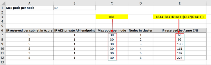
You could make use of the following very simple Excel table to help you with your capacity planning.
An additional reserved IP has been added in column B which represents the private endpoint of a private AKS cluster.
Highlighted in yellow are the formulas used in the indicated columns with the red arrows (C and E), the other columns hold static values.

If you are looking to fit more nodes in your cluster, keep an eye on the size/SKU of your nodes/VM’s as you might not need as much compute on individual nodes since you will be able to achieve the same total amount of memory and CPU with more nodes of a smaller size. The Kubernetes scheduler will then do the job of spreading evenly the workload across all the nodes.
- AKS cluster pods capacity
As seen earlier in order for pods from your applications (user pods) to get IP’s assigned in the cluster, those IP’s must be reserved by Azure CNI at the creation of each node and they must not already be assigned to system pods.
Let’s try to determine how many user pods can be created in a 3-node cluster configured with the default max pods per node (30).
In AKS 1.17.4 by using the following command ‘>kubectl get pods -A -o wide’ right after the deployment of your AKS cluster, you can notice that there are 16 system pods running (no add-ons) using 5 different IP addresses (some pods such as kube-proxy or azure-ip-masq-agent share the same IP as the nodes they are hosted in, hence the difference).
At the end, 3 nodes x 30 max pods per node – 16 system pod = 74 user pods can be created.
N.B: keep in mind the existence of Kubernetes system daemonSet resources to understand the spread of the system pods across all the nodes of the cluster.
It does not matter here that there are more IP’s reserved by Azure CNI and available in the cluster 3×30-5=85 since the max pods per node is a hard limit that cannot be exceeded.
I hope you now fill much more confident in designing and configuring your AKS clusters to meet all your requirements and needs.
Ouissame Bekada
Senior Premier Field Engineer, Cloud and Infrastructure, France
by Scott Muniz | Jun 18, 2020 | Uncategorized
This article is contributed. See the original author and article here.
What-if analysis is a great use case for Azure machine intelligence techniques. Bart Czernicki, Principal Technical Architect with the Microsoft Machine Intelligence team, shows you how in his sample web app for baseball decision analysis based on ML.NET and Blazor called the Machine Learning Workbench. He shows you an example architecture on Azure and provides all the source code on GitHub.
Bart has created the Machine Learning Workbench as a web app with a friendly interface to a powerful what-if analysis engine. It takes historical and current baseball data and uses AI and machine learning models to make informed predictions.
The solution delivers National Baseball Hall of Fame insights, but the architectural approach applies to decision analysis systems in general, from building a fantasy baseball team to forecasting financial scenarios for budgeting and planning.
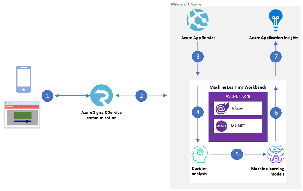
The Machine Learning Workbench is built in ASP.NET core using ML.NET, an open-source framework that provides the inference engine, and Blazor Server to render the interface. Azure SignalR Service brokers communications between Workbench and the user interface.
 Machine Learning Workbench architecture on Azure
by Scott Muniz | Jun 18, 2020 | Uncategorized
This article is contributed. See the original author and article here.
Out of the box, Azure Sentinel provides 90 days of data retention for free. In some parts of the world and within certain industries, there are regulations that organizations must adhere to which require data retention up to 7 years or longer. The current challenge is that the max retention for Log Analytics workspaces is 2 years. There has been a need for a solution that will allow for more time and cost saving by moving logs to cold storage. This blog is going to detail how logs from a Log Analytics workspace can easily be moved into long-term cold storage in order to comply with retention standards as well as reduce costs using this Playbook.
End Results:
 Logs are put into Blobs within folders that are labeled by data type.
This post is going to be in-depth as it breaks down how the Playbook is going to operate.
TL:DR The end result once the Playbook is run is a folder system with Blobs within a storage account and container. The folders are labeled with and contain the data types that have been chosen for back up. Each Blob in the folder will contain a backup of logs for each data type in hourly blocks. Each Blob can be queried in a Log Analytics workspace using the externaldata operator and a SAS token URL generated for the Blob.
Link for the Playbook if needed: https://github.com/Azure/Azure-Sentinel/tree/master/Playbooks/Move-LogAnalytics-to-Storage
*Note: If your Blobs are a size of 2B, there was no information for that time block or data type.
Pre-requisites:
- Log Analytics Workspace
- Azure Storage Account or permissions to create a new one
- One storage container or permissions to create one
- The Logic App
For auditing and investigative purposes, raw data and logs may need to be stored long term for regulatory compliance. This can be achieved through a Playbook that queries the logs from the workspace that are about to expire and moves them to a storage account of your choosing. The Playbook utilizes Log Analytics API when performing the query. An important piece of information to note is that the API has a limitation of 500,000 rows of data per request. This means that if any data type contains more than 500,000 rows of information, it will require the Playbook to run a Log Analytics API pull more than once to get the data. In order to avoid this issue, the Playbook breaks up data for each day into hourly blocks in order to efficiently and carefully back up all desired data. Each time that the Playbook is run, it reviews each data type within your workspace that should be backed up, goes through the logs for those data types, and moves the logs to storage, labeling each backup with the data type, the date of the log, and the hour for the time block.


The app is comprised of many steps and variables in order for it to work. The pieces are the following:
- Recurrence trigger – Automatically run the app daily without needing manual input.
- hoursCount – Counter variable that is used for tracking which hour the Playbook is on for exporting data. Starts at 0 for midnight and caps at 24.
- startDate – Oldest date in a range that the queries will be using. Value is set to the current date minus 89 days (formatDateTime(addDays(utcNow(), -89),’yyyy-MM-dd’)). This serves as the starting point for the time range to pull data from.
- endDate – Similar to startDate, this variable serves to be the tail end of the time range. This value is set to the current date minus 88 days (formatDateTime(addDays(utcNow(), -88),’yyyy-MM-dd’)). The time range between startDate and endDate are now 89 days ago and 88 days ago. The purpose for this is to move logs to storage 24 hours before they are deleted from the workspace.
- excludedDataType – This variable is used to hold a list of data types that should not be backed up when running the Playbook. The list of options will be used in the query that checks to see which data types should be backed up. It is recommended that the data types chosen are logs that are noisy or are not important.
- Query #1 – This query sets which log types should not be included based on the excluded variable. The query then checks the usage details to see which data is present in the workspace between 89 days ago and 88 days ago.
- Compose – Composes the data for parsing for future use in the app.
- Parse JSON – Parses the message from the query so that each item from the query results can be referenced later in the Playbook. The sample JSON for the step is provided in the template.
- All of the details are then passed into a ForEach loop that then goes into an until loop that checks if hoursCount is 24. Each time that the logs are exported for a data type, it will increment the counter by 1 until it hits 24, then moves onto the next data type.
- Query #2 – This query takes in the value of each data type and takes the logs from hours 0-23 for the day in hourly blocks.
- Compose #2 – The results are composed into a message for sending to the Blob.
- Create Blob – A new Blob is created with the title of the data type, the date, and the hour for which the logs are from. These results are sent to the new Blob and will be housed in the container that you have named.
Depending on how much data is within each table, the Playbook can take 2 to 10 minutes per table depending on how much each table has.
Deployment of the Template:
There are two options for deploying the template:
- deployment button directly in GitHub
- manual deployment via deploying the JSON of the Playbook in the Azure Portal
If using the manual option, please refer to the README for the Playbook.
Using an Existing Storage Account:
In the event that an existing storage account is preferred, it can be set up within the Playbook. The following must be done:
- Go to the Azure Portal
- Go to the Playbook
- Go to Logic App Designer
- Go into the loop
- Go to the Blob action
- Click on ‘change connection’
- Click add new
- Choose the desired storage account
- Give the connection a name
- Click create
- Update the container name to be one from the existing storage account
Granting Permissions:
The Playbook is going to need proper permissions to run. It requires at least Blob Storage Contributor in order to create new Blobs within the data container. In order to provide the permissions:
- Go to the Azure Portal
- Go to Logic Apps
- Choose the Logic App
- Go to identity
- Enable ‘system assigned’ identity
- Click save
- Go to either the subscription or the resource group that the storage account that is being used is in
- Go to access control
- Click add
- Choose add role assignment
- Under ‘assign access to’ choose Logic App
- Find your Logic App
- Select it
- Choose the role ‘Blob storage data contributor’
- Click assign
Query the data:
 Querying the data from 3 different blobs in order to see the data that was stored.
Once the data is in storage, it is still possible to query the day but in a smaller capacity. Querying the data now uses an operator called ‘externaldata’ which requires you to use a SAS token URL generated by the Blob in order to pull the data from it. The process also requires that each column be defined so that it can properly map the data to the correct column. An example of what the query would look like would be:
- let ActivityLogs = externaldata (TimeGenerated:datetime, OperationName:string, OperationNameValue:string, Level:string, ActivityStatus:string, SubscriptionID:string)[@”SAS TOKEN URL FOR BLOB”] with (format=”multijson”,recreate_schema=true); ActivityLogs
This query
- Creates a variable that will become the table
- Establishes what the columns will be and their value type
- Once the columns are made, the SAS token URL is inserted
- Multiple URLs can be inserted in order to pull from multiple Blobs. Just separate the two by a comma and have them in their own quotations
- The query then calls the table that you have created, this pulls in the logs from the Blob and routes the data to the columns that were created
This query is going to pull the AzureActivity information from the Blob and maps the data to the associated columns. It is recommended to base your schema on the existing tables that were backed up in order to avoid any issues with parsing the data. In this case, AzureActivity was used as the reference for the associated logs that were in storage.
More information about external data: https://docs.microsoft.com/en-us/azure/data-explorer/kusto/query/externaldata-operator
Summary:
With this Playbook, you now have control over logs being moved into long-term storage. This will be handy for existing data that is in the workspace that Sentinel is using when the retention period for the data runs out. This, in combination with the ability to query data from cold storage, allows for regulatory compliance and reduced costs while maintaining Sentinel log and Log Analytics usage for business operations.
This solution would not have been possible without the effort and great help from @Matt Egen, @Chris Boehm , and Rin Ure.
by Scott Muniz | Jun 18, 2020 | Uncategorized
This article is contributed. See the original author and article here.
Earlier this year, we released the ability to create new Visio diagrams from within Teams. As part of the effort to make collaborating on Visio diagrams within Teams experience, we now bring you Visio as a tab to help you easily access and manage the Visio files you need or interact with the most.
Visio tabs in Teams allow team members to access services and content in a dedicated space within a channel or in a chat. This lets the team work directly with tools and data, and have conversations about the tools and data, all within the context of that channel or chat.
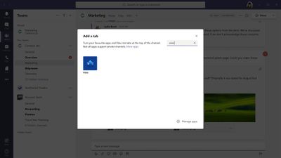
Owners and team members can add more tabs to a channel or chat by clicking Add a tab at the top of the channel or chat.

Either to a Teams channel or create a new one from within Teams . That Visio file then can be converted to a tab with a single click, as shown below.

Visio can help you in a variety of roles across industries. Here are just a few use cases to spark ideas for your company.
- Increase productivity when coauthoring a diagram in real time – Visio diagrams are typically created by multiple authors (for example, an enterprise architect, a database architect, and an application architect will work together to create an architecture diagram for a new module). By pinning the diagram as a tab, you can ensure that coauthors are able to quickly access and edit the diagram when and where needed—without wasting time on searching for the file.
- Keep important processes at your fingertips – Organizations often have processes that need to be followed to perfection. For instance, in Business Process Outsourcing (BPO), customer representatives need to follow specific steps to solve user queries. When captured in a Visio file, these business processes can be added as a tab in a Teams channel for your employees to easily reference at any time, from almost any device. Diagrams can also be edited in real time with a Visio Plan 1 or Plan 2 license—with changes available to others immediately.
- Get up to speed quickly – Oftentimes, a team member who wasn’t involved in the initial creation of a diagram will need a better understanding of a diagram in order to convey a concept to outside stakeholders. For example, an Azure consultant needs to review Azure architecture with a client. By converting your diagram as a tab in Teams, you can allow team members to quickly access, review, add comments, and converse in context to gather necessary information.
- Simplify the brainstorming and iteration process – Business professionals from a wide range of industries brainstorm on business diagrams like SWOT analysis, Venn diagrams, pyramid diagrams, etc. These diagrams typically require several iterations, taking into consideration input from multiple stakeholders. By creating a tab in a relevant Teams channel or chat, you can simplify the review process by giving all stakeholders quick and easy access to your diagram(s).
Adding a tab in Teams is available to , but editing is only available for those with a Visio Plan 1 or Plan 2 subscription. Compare plans to decide which option is best for you or try Visio Plan 2 for free for 30 days.
We invite you to submit ideas for future feature releases on our UserVoice site. For questions about recent releases, please email us at tellvisio@microsoft.com. To stay current on the latest Visio releases, follow us on Facebook and Twitter, visit our blog, and engage with us on the Visio Tech Community.

Recent Comments