This article is contributed. See the original author and article here.
In the Planning to perform Proof of Concept guide Part 1 , we discussed the necessary steps for a successful POC such as : Understanding network security requirements for the different resources, creating indices to measure successful security POC, the security standards to be reviewed, how to create timelines to work on security lapses and how to monitor the network for improvement.
In this second part, you will learn to deploy and verify the environment to validate some of the sample Proof of Concept mentioned earlier. If you know the elements required already, you can go straight to the components (WAF, Azure Firewall or DDOS) in the sections below.
Permissions
To provision and configure resources, it is necessary to have Network Contributor access or a more permissive/administrator role.
Azure Network Security Demo Environment.
An azure pre-configured test deployment kit for POC is available in this repository. By agreeing to the terms, you can use this environment for most of the POC in this guide e.g. DDOS protection, OWASP top ten core rule set, Virtual network security etc. This environment has been configured to have most of the tools you would need and they have been connected by network rules that you can verify.
(Note: Resources in this deployment will incur some charges. Make sure to remove resources once POC is completed)
Deployment
For portal deployment, Click on the Deploy button below to go to the deployment page.

- Create or use an existing resource group/region for the deployment.
- Provide username/password for access to the VMs.
- If you have a Workspace Name and Workspace Subscription for diagnostics log, insert it here. This is required for log access. If you do not have one, you can set it up here. This is highly recommended for all Azure resources.
- Click Create or Purchase to begin deployment.
To deploy the demo environment using PowerShell, follow these steps :
Connect to your Azure environment:
PS C:windowssystem32> Connect-AzAccount
Create a resource group in your region:
PS C:windowssystem32> New-AzResourceGroup -Name demoresourcegroup -location "westus"
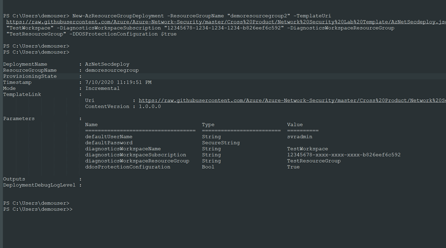
Deploy the demo environment using the template in the GitHub repository
PS C:windowssystem32> New-AzResourceGroupDeployment -ResourceGroupName "demoresourcegroup" -TemplateUri https://raw.githubusercontent.com/Azure/Azure-Network-Security/master/Cross%20Product/Network%20Security%20Lab%20Template/AzNetSecdeploy.json -DiagnosticsWorkspaceName "TestWorkspace" -DiagnosticsWorkspaceSubscription "123456789-xxxx-xxxx-xxxx-b826eef6c592" -DiagnosticsWorkspaceResourceGroup "TestResourceGroup" -DDOSProtectionConfiguration $true
Note:
The following values in the last step should be updated for your account: Subscription ID, Log Analytics Workspace name and Resource Group for Log Analytics workspace.

In view of the deployment type you use,, the demo environment should include the following resources upon deployment:
- 3 Virtual Networks (1 Hub that hosts the firewall and 2 Spoke VNets)
- 1 Application Gateway provisioned with Web Application Firewall
- 1 Azure Front door with WAF enabled.
- 1 Azure Firewall (deployed in Hub VNet via Azure Firewall manager)
- 3 VMs (2 Windows and 1 Kali Linux)
- 2 Public IP addresses (1 for the Firewall and 1 for the App Gateway)
- DDoS protection enabled for the Hub virtual network.
- 2NSGs.
- Route table
- Web App (Demo web app to perform vulnerability tests)
The resources have been connected in a simple hub and spoke topology as seen in the diagram below.

The hub is a virtual network(VN-HUB) in Azure that acts as a central point of connectivity to your on-premises network. This is where you want to place the firewall. The spokes are virtual networks that peer with the hub and can be used to isolate workloads, thereby modeling a common deployment scenario for most network designs. This network diagram uses these two basic connections to keep it simple
- The hub virtual network will use virtual gateway access for the firewall to route traffic.
- The Spoke virtual networks will use the subnets to host the azure resources (VMs etc.)
for other additional considerations
- (If the planned spoke is in a local area network that requires a VPN connection through an external public interface, use this link: On-Premise-Network connection to Gateway)
- If you require multiple spoke-to-spoke connections, you may soon run out of virtual network peering allowable, User Defined Routings may be used to create routes in the router to forward traffic. See more on Multiple-Spokes-VNET-Connections
Azure Network Security Components
Web Application Firewall (WAF)
Web Application Firewall protects web apps from vulnerabilities and attacks without modification to back-end code, preventing the application from outage, data loss and attacks.
WAF policy
WAF is configured through HTTP and HTTP/s listeners by setting up a WAF security policy and applying it to Azure Front Door, Application Gateway or CDN.
WAF: Azure Application Gateway
WAF when combined with Application Gateway work as a web traffic load balancer and provide L3-L7 security for your back-end pool: VMs, VM scale sets, IP addresses and app service. For more information on the App gateway go to AppGateway features.

To view the WAF policy configured with the Application Gateway in the demo deployment:
- Go to the test Resource group that was created “demoresourcegroup” and click on SOC-NS-AGPolicy to view the WAF policy for the Application Gateway. The managed and custom rule sets can be used to effectively allow/deny traffic when in prevention mode.

Detection mode allows traffic to pass through while logging the attack events. Use this mode to observe and learn traffic behavior at the beginning for proper tuning, then switch to Prevention mode. This is the recommended configuration
The request body size (KB) can also be edited here, and you can configure what parts of requests to exclude under the Exclusions area
Managed rule set: This is the OWASP top vulnerability attacks list. It uses the OWASP 3.1 or most recent core rule set.
Custom rule: To block an IP from Canada or geolocation of choice: Click +Add custom rule.
- Custom rule name: type “blockCanada”.
- Status: Enabled, Rule type: Match, Priority: 1 or as desire
- IF Matchtype: dropdown- Geolocation
- Select Canada. You can select more than one.
- Then: Select Deny traffic (Or redirect to a custom page).
- Click Add
To view the Custom rules set up earlier in the WAF policy, click on Custom rules. 3 custom rules can be seen. Other features of Application Gateway when combined with WAF include protection from crawlers and scanners, bot mitigation, cross site scripting etc.
The OWASP Juice shop website, a site with vulnerabilities common to web apps, has been deployed in the App Gateway with WAF enabled for this scenario.
- Go to the demoresourcegroup and click on the Application Gateway configured with the demo deployment on the list: In our case: SOC-NS-AG-WAFv2.
- In the Overview section, on the right, the front-end private and public IP addresses associated with the Application Gateway are shown.
- Click on the Public IP to confirm the OWASP Juice web application is accessible.

WAF: Azure Front Door
Azure Front Door provides a secure global traffic delivery solution for your backend resources. It uses anycast protocol to improve global connectivity and availability using smart health probe, URL Path Based Routing, Multiple site hosting, Session Affinity, App Layer security, URL redirection.
The URL/IP for your web application and a Web Application Firewall policy are required to configure WAF for your environment behind Azure Front door.
To view the Front door and WAF configured with this deployment, go to the test resource group demoresourcegroup, and click the Front door in the list. In this case, Demowasp-jfyg5g7ve5w6a
On the Overview page, click on the Frontend host link on the right to view the web app. It should be a link with azurefd.net as part of the URL. E.g. https://Demowasp-7tzl765vvi3qe.azurefd.net
Back on the same Front door page, click on Front Door designer
a. The front-end domain configured can be seen. Click on the demo app.
– The session affinity and WAF features can be toggled as desired.
– The policy applied can also be changed if you have created other policies.
b. Under the Backend pools, the OWASP app can be viewed.
This is your app or container. Click the app to edit configurations such as health probes and load balancing options. Multiple backend hosts can also be added. In this case, we have added a back-end pool using the public IP address for our OWASP Juice shop application.
c. Lastly, Routing rules: This is connection between the frontend/domains and the backend pool from a and b above.
If an additional back-end pool is needed, you can add them here. Also, Path Based routes can also be set up in this window for content distribution and management. If you need to permit Front door access to your Keyvault, check certificate permission

Under Settings, select Web Application Firewall. The WAF policy for this front door SOCNSFDPolicy has been linked.
When Front door is combined with WAF in this way, rate limiting can be configured to manage access to your backend resources.
Visit the Azure documentation to see examples of custom rules with PowerShell and to configure the rules with Azure portal.
DDoS
To view the DDOS protection standard deployed, go to demoresourcegroup and click on SOCNSDDOSPLAN (or the name given to your DDOS plan in your resource group). You can enable and disable the plan here. DDOS can only be enabled for a Virtual Network. You can configure one DDoS protection plan for your organization and link virtual networks from multiple subscriptions to the same plan. More information on the DDOS plan here.
The test is performed using the public facing IP address to the resource’s endpoint. Apps may be placed in the Backend pool of App Gateway or set up in VMSS- all placed in the protected VNets, as shown in the network diagram above.

- Go to the demoresourcegroup and click the VN-HUB. The VN Hub is the virtual network protected by the DDOS protection standard.
- Under Settings, Click DDoS protection. If enabled, the two subnets in the Hub Virtual network: SOC-NS-AG-WAFv2 and SOC-NS-FW are protected by the DDOS protection plan.
Go to the Application Gateway. To view the Front-end Public IP, Go to the right-hand corner of the Overview page.
Next, we confirm how to set up the alerts for the DDOS protection metrics.
- Go to the top search bar on the page and type in Monitor, Select Monitor.
- Under Alerts, select Manage alert rules, select +New Alert rule. Under Scope, choose your subscription and its resource group, select a Public IP. In this case: SOCNSAGPIP (the Application gateway public facing IP address)
- For Condition, Click Select Condition to add a new signal. Select “Under DDoS attack or Not”. Aggregation: Max, Threshold 1.

- Action Group: Enter a name and provide an email address or phone number for notification.
- Under Settings, Go to Diagnostic settings, enable the public IP SOCNSAGPIP
Visit the web resources for additional information on DDOS adaptive tuning and DDoS Protection telemetry, monitoring, and alerting . We have now set up the test environment to observe DDOS protection metrics.
Azure Firewall
The “demoresourcegroup” has a firewall policy managed via the Firewall manager in the secure hub VNet for the POC scenario.
Azure Firewall Manager enables centralized management of your firewalls in your network. In this case, we have only one Firewall. More on Azure Firewall Manager
To access the firewall configuration in the test deployment,
- Go to demoresourcegroup, Click on Firewall (In this example: SOC-NS-FW).
- Under Settings, Go to the Firewall Manager. Click on the Azure Firewall Manager. Click “Azure Firewall Policies”.
- The firewall Policy properties can be seen. Click the policy (SOC-NS-Policy).
- Click on Rules under Settings to see the rules. There are 3 different rule types in the collection: Network, Application and DNAT rules. The VMs can be accessed through the NATted public IPs in the DNAT rules

Azure Firewall design is explicit deny-by-default. You can configure the rules for your traffic. As seen in the image above, the Azure firewall in the demo has been configured with this the following:
- The 2 spoke VNETs do not have direct connectivity between their subnets.
- Application rules are set up to grant and manage access using FQDN of search engines: Bing and Google for your test.
- Network rules to permit only SMB, RDP and SSH and deny all others have been configured.
DNAT rules to permit access from unique NATted IPs for VM access via the firewall have been configured
You may insert additional rules for your POC and test for connectivity.
Conclusion
Performing a Proof of concept may be done for several reasons: trying out a new network tool, introducing a new resource, capacity planning, performance, and response, trying out network architecture etc.
When you have performed the Proof of concept, review the outcome with the reference model expectation in terms of established indices, success indices, security standards and timelines to work on newfound evidence.
Also, confirm that you can monitor logs as discussed in the concluding session of part 1 of this series. Part 3 and beyond will focus on deep dive testing of these scenarios
Brought to you by Dr. Ware, Microsoft Office 365 Silver Partner, Charleston SC.

Recent Comments